¶ Introduction
This document describes two possible network setups for SERVERware:
-
A design without redundancy at the network level.
-
A design with network-level redundancy, which provides high availability of services.
For systems that need to be highly available and fault-tolerant, the network should be planned with redundancy at every level. In other words, all key network components must have a backup. Here we will focus on redundancy at the switching level (Layer 2). Routing (Layer 3) depends on the overall network design and can vary from case to case.
¶ Network Design Hardware
The network setup is based on Cisco WS-C3750G series switches. This is a Layer 3 switch that supports all the protocols and mechanisms needed for redundancy.
Performance:
- 32 Gbps switching fabric
- Stack forwarding rate up to 38.7 mpps for 64-byte packets
- Forwarding rate: 6.5 - 38.7 mpps (depending on model)
Features used for redundancy:
-
Cisco CrossStack UplinkFast (CSUF) for fast spanning-tree convergence (under 2 seconds) with StackWise
-
1:N master redundancy, where any stack member can take over as master
-
Cross-Stack EtherChannel, allowing EtherChannel across different stack members
-
IEEE 802.1w Rapid Spanning Tree Protocol (RSTP) for fast convergence and distributed processing
-
Per-VLAN Rapid Spanning Tree (PVRST+) for quick reconvergence per VLAN
-
Stacked units operate as a single spanning-tree node
-
Bandwidth aggregation:
- Up to 16 Gbps with 10-Gigabit EtherChannel
- Up to 8 Gbps with Gigabit EtherChannel
- Up to 800 Mbps with Fast EtherChannel
¶ SERVERware - Non Redundant Network Design
System Overview
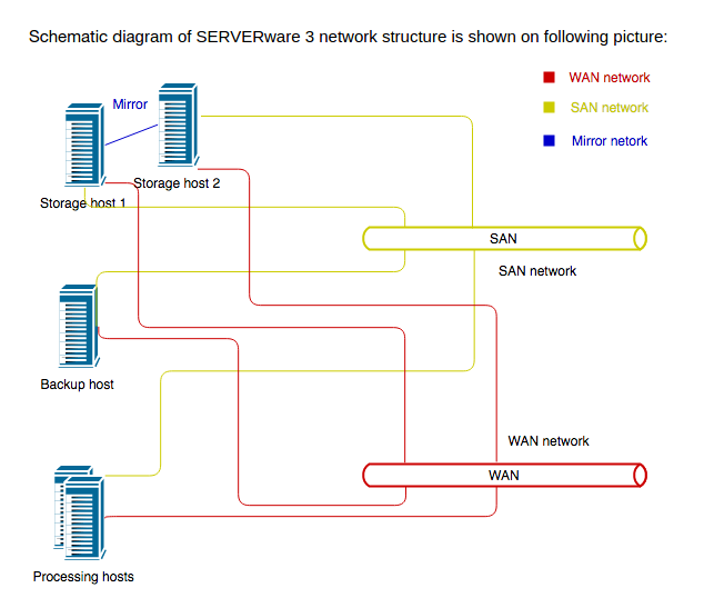
The system consists of three types of hosts: storage hosts, processing hosts, and a backup host.
- Storage hosts: Two hosts are set up in a mirrored configuration, providing storage for the processing hosts via the SAN (Storage Area Network).
- Processing hosts: These run VPS instances, which access storage over the SAN. VPSes deliver services to customers over the WAN.
- Backup host: This host stores VPS backups. It transfers data from the storage hosts to its local disks over the storage network.
Network Considerations
SAN traffic can be heavy, so it should be kept separate from other network traffic.
-
In larger setups with many processing hosts, it's best to use a dedicated switch just for SAN traffic.
-
In practice, the same switch is often used for both SAN and general network traffic. If that's the case, VLANs should be used to separate the traffic:
- A SAN VLAN handles storage traffic.
- Other traffic can stay on the default (native) VLAN.
- Optionally, a separate VLAN can be created for voice traffic, with QoS set to give it priority.
Next schematic diagram shows SERVERware network with one Cisco switch (no network redundancy):
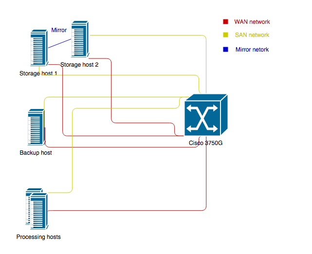
To separate SAN traffic from other traffic on network, we can use VLANs and configure all ports which belongs to SAN network to be members of SAN VLAN.
Here is example of cisco configuration which shows how to configure VLANs on ports:
...
interface GigabitEthernet0/0/1
switchport access vlan 20
switchport mode access
!
interface Vlan20
description “SAN VLAN”
no ip address
...
¶ SERVERware - Network Redundancy
System Overview
The SERVERware network is built for redundancy using two Cisco WS-3750G switches configured in a stack. The switches are connected with stacking cables, which provide a 32-Gbps stacking bus. To maintain redundancy, each host connects to both switches. This means every SAN and WAN connection requires two Ethernet interfaces—one to each switch.
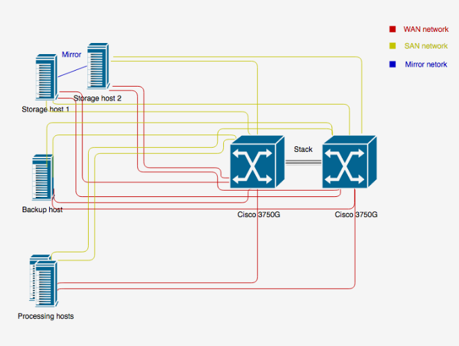
This network design allows redundancy on network level. In case that one switch failed, other switch will take over network traffic. Cisco switch support EtherChannel over Switch Stacks which is necessary and without it network redundancy will not work.
Same as we provide separation of SAN traffic in non redundant network design, also in redundant network design, to separate SAN traffic from other traffic we will configure appropriate VLANs. Here is example of Cisco switch configuration with network redundancy and VLANs configured to separate SAN traffic:
interface Port-channel5
switchport access vlan 20
switchport mode access
!
interface Port-channel6
switchport access vlan 20
switchport mode access
!
interface Port-channel7
switchport access vlan 20
switchport mode access
!
interface Port-channel8
switchport access vlan 20
switchport mode access
!
…
interface GigabitEthernet1/0/25
description Controller 1 SAN NIC
switchport access vlan 20
switchport mode access
channel-group 5 mode active
spanning-tree portfast
!
interface GigabitEthernet1/0/26
description Controller 2 SAN NIC
switchport access vlan 20
switchport mode access
channel-group 6 mode active
spanning-tree portfast
!
interface GigabitEthernet1/0/27
description Backup SAN NIC
switchport access vlan 20
switchport mode access
channel-group 7 mode active
spanning-tree portfast
!
interface GigabitEthernet1/0/28
description Proco SAN NIC
switchport access vlan 20
switchport mode access
channel-group 8 mode active
spanning-tree portfast
!
…
interface GigabitEthernet2/0/25
description Controller 1 SAN NIC down left
switchport access vlan 20
switchport mode access
channel-group 5 mode active
spanning-tree portfast
!
interface GigabitEthernet2/0/26
description Controller 2 SAN NIC down left
switchport access vlan 20
switchport mode access
channel-group 6 mode active
spanning-tree portfast
!
interface GigabitEthernet2/0/27
description Backup SAN NIC down left
switchport access vlan 20
switchport mode access
channel-group 7 mode active
spanning-tree portfast
!
interface GigabitEthernet2/0/28
description Proco SAN NIC down left
switchport access vlan 20
switchport mode access
channel-group 8 mode active
spanning-tree portfast
!
interface Vlan20
description "SAN VLAN”
no ip address
!
In this setup, the two SAN Ethernet interfaces of Controller 1 are connected to port 25 on both Switch 1 and Switch 2. These two ports are combined into an EtherChannel, Port-Channel 5, which is assigned to VLAN 20—the SAN network VLAN. Controller 2 is connected similarly, using port 26 on both switches. These ports form Port-Channel 6, also assigned to VLAN 20 for the SAN network. The backup and processing hosts are configured in the same way. This setup provides network-level redundancy for all hosts.