-
The main problem in regards to the VPS storage until SERVERware 3 was the VPS duplication feature which would see data loss happening in between duplication cycles. Unlike SERVERware 1.x, version 3 does not rely on VPS duplication to provide VPS failover functionality. By using a shared storage, SERVERware 3 ensures that all VPS data is present in the event of a processing host failure. Another processing host will connect to the appropriate VPS volume exported by the storage server, after which the VPS will start running with the most recent data.
-
¶ Standalone Edition: Uses a single server for both processing and storage needs. Disks are paired to make redundant array(s) for data protection.
-
¶ Mirror Edition: Uses two real-time mirrored redundant servers in Active/Passive configuration, where disks are paired across RAN (Replication Area Network).
-
¶ Cluster Edition: Uses redundant shared storage built with two servers in real-time mirror, and processing hosts connected to shared storage.
-
Space, which is determined by number and size of disks available in network storage pool.
-
Storage speed, which is determined by performance of individual disks and interface they are connected with, like: SAS, SATA, RAID
-
SAN capacity
- Bandwidth
- Latency
-
RAN capacity
- Bandwidth
- Latency
- Importance of working RAID battery
- Importance of UPS and dual power
- Remote power management support (remote reset/power off/on)
- Remote access to BIOS
- Remote SSH console access
- A public IP assigned to KVMoIP
- If KVMoIP is behind firewall/NAT, the following ports must be opened: TCP (80, 443, 5100, 5900-5999)
- DVD image burned on to a DVD and inserted into DVD drive
- USB image burned onto 2GB USB drive and inserted into operational USB port
-
NETSTOR pool without HW RAID
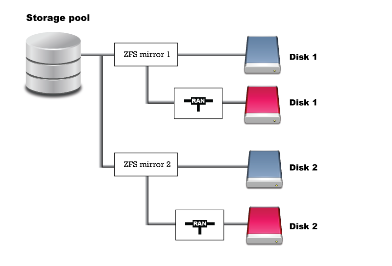
-
NETSTOR pool with HW RAID
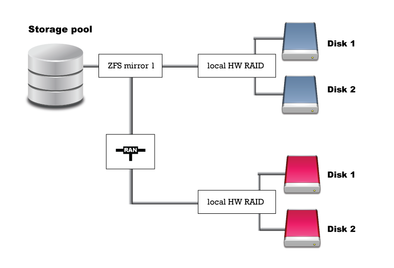
- Exit - Choose this option to exit installation wizard. This option will open live system command line shell.
- Verify Media - This option will go trough the installation media files, match them against previous stored checksum and check for corruption.
- Next - Proceed to the next step.
- Network - Configure IP address for the remote access to the installation wizard.
-
Striped: This option optimizes performance by striping data across multiple disks, enhancing read and write speeds.
-
Mirrored: Selecting this option creates a mirrored ZFS pool, enhancing data redundancy and fault tolerance.
-
RAIDZ: This option allows users to configure a ZFS pool using the ZRAID (ZFS RAID-Z) technology, providing a balance between performance and data protection.
- A redundant storage server which holds virtual resources like virtual server volumes and templates.
- Virtual private server's hosts that use Linux Containers (LXC) is virtualization technology.
- Agents and tools running on hosts. These tools provide local management for virtual private servers.
- Controller, a centralized management platform for the SERVERware environment. It provides a graphical user interface which can be used to view, provision, and manage resources. It runs on the storage server within a dedicated Linux container.
- A database that tracks the states and changes of the environment.
- Networking links the environment together. This includes physical network links as well as logical subnets.
- Network - A SERVERware network is the highest level container for all physical and logical resources within a managed virtual environment. It is a collection of hosts, domains, virtual servers, storage, and networks.
- Storage - SERVERware uses a centralized shared storage system for virtual server volumes and templates. SERVERware storage is implemented using ZFS as a storage engine and Internet Small Computer System Interface (iSCSI) protocol for exporting VPS volumes to the processing hosts.
- Hosts - A SERVERware host is a physical server that hosts virtual servers.
- Logical Subnets - SERVERware defines a couple of logical subnets to the physical network interface cards. Logical subnets are used for traffic management, storage mirroring, and storage, traffic between storage and processing hosts.
- Domains - A SERVERware Domain is a logical group of physical, virtual resources and users.
- Virtual Private Servers - A VPS (Virtual Private Server) is equivalent to a dedicated physical server. Since it is software-defined, it is much more easily configured and managed.
- Virtual Networks - Create virtual networks inside the SERVERware using either IPV4 or IPV6 protocols.
- Templates - A Template is a pre-configured VPS that is loaded with all the necessary software for its specific role. A couple of Templates can be used together to form an even more specific VPS.
- Backups - Backup is a feature that is used for data protection and recovery.
- Archiveing - Archive PBX calls and CDRs in a safe place and free up space on the storage.
- GRS - Ability to replicate the VPS from SERVERware to another (geo remote location) SERVERware.
- Users - SERVERware allows a couple of different user accounts to be created. Accounts can have different roles and various permission levels.
- System Logs - A SERVERware System Log is a logging system that records events that occur in SERVERware. It can be used for system management, analysis, and debugging.
- Alarms - Alarm is an alert that can be triggered under certain abnormal operating conditions. Alarms can be received by a group of recipients via various notifications.
- Statistics - SERVERware statistics collects resource usage data. Data is stored and presented for Hosts and VPSs.
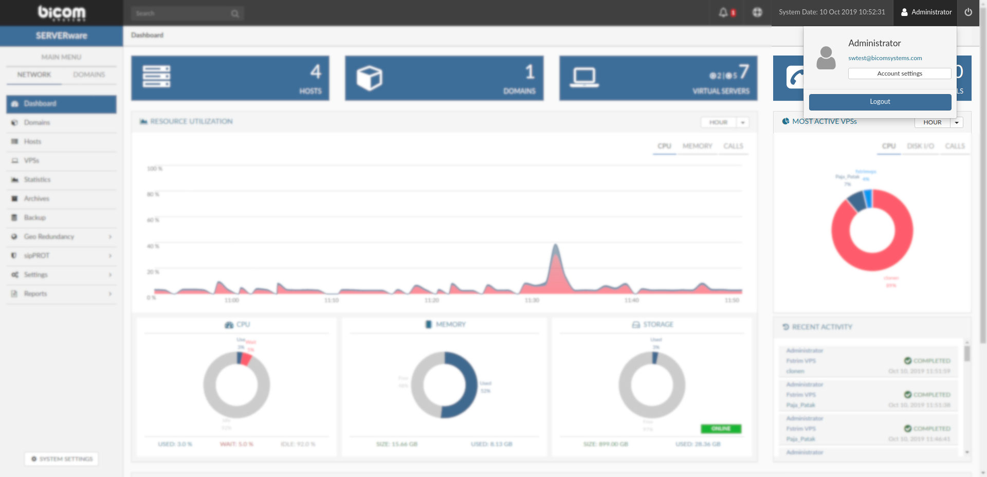
- At the title bar of the Web Control Panel, click on the username (Administrator, YourName, etc..), then click on Account settings to enter the Account settings menu.
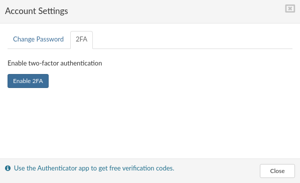
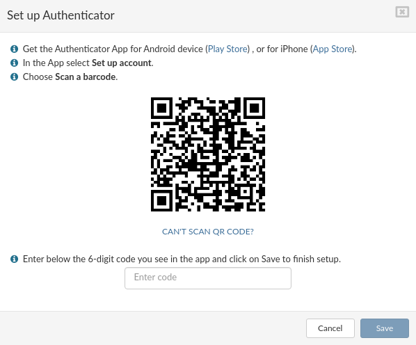
- Account settings menu will popup. At the Account settings menu select 2FA and click on Enable 2FA
- Follow the instructions from '''Set up Authenticator''' window and click '''Save'''
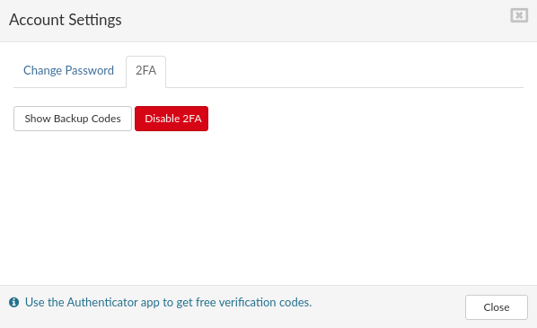
- On this step you can disable '''2FA''' or view '''Backup Codes''', this window is also a confirmation that '''2FA''' is enabled for specific user. It is possible to '''Change Password''' on this step for specific user. Click '''Close'''.
-
To start using '''2FA''' please logout from SERVERware panel and login screen will appear. Enter your username and password and click '''Login'''
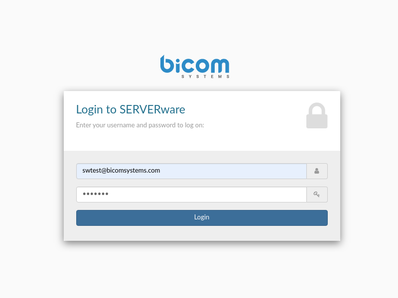
-
If entered username and password is correct new screen will appear, if username or password is incorrect you'll get error '''Invalid Credentials!'''. Enter code from your Authenticator app or an unused backup code to complete login procedure.
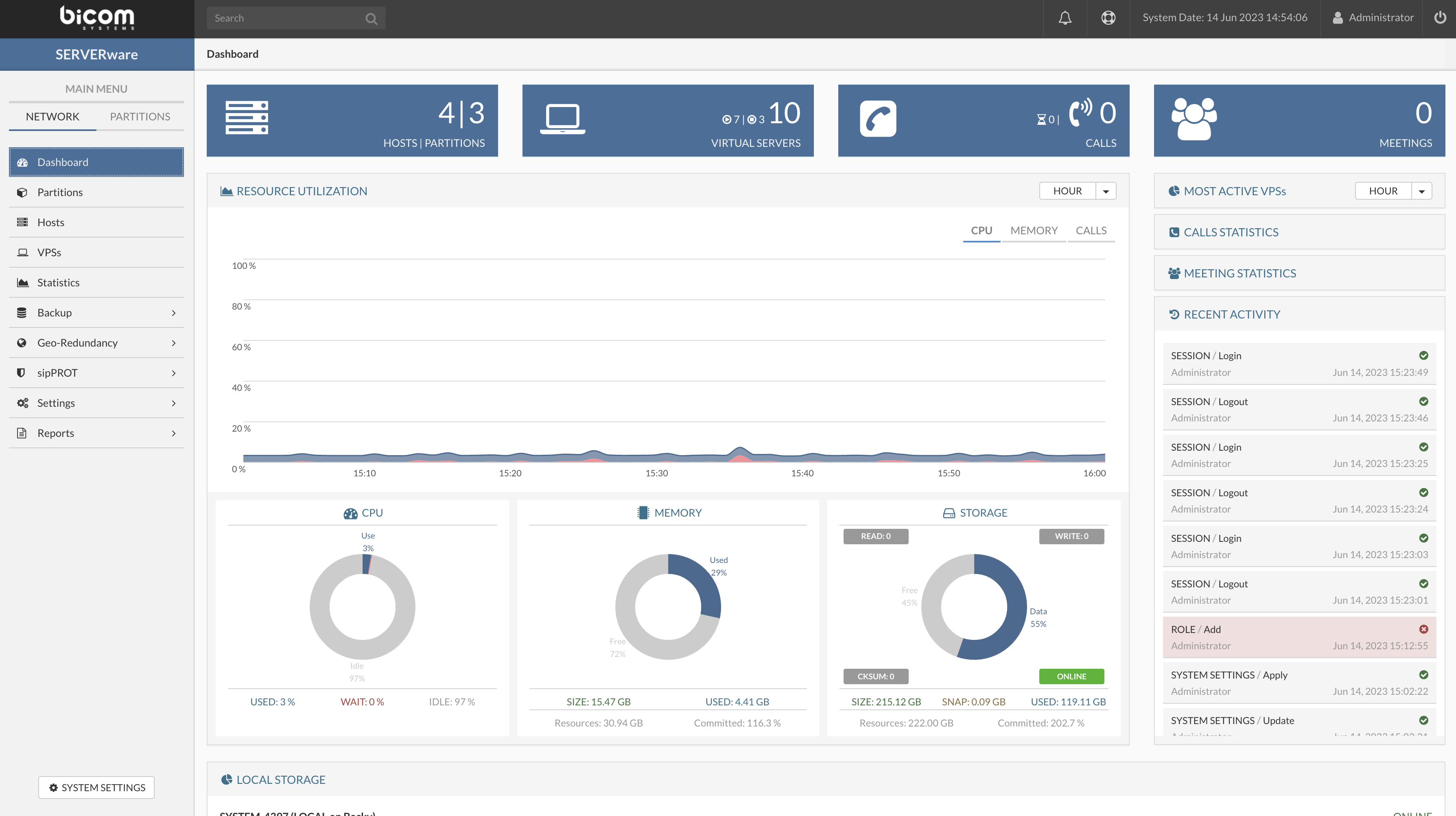
- Running VPSs Indicator - Display the total number of VPSs as well as the number of running VPSs.
- Active Calls Indicator - Display a total number of concurrent calls on all running VPSs within the SERVERware network.
- CPU Usage Indicator - Display CPU usage on primary storage host.
- MEMORY usage indicator - Display memory usage on primary storage host.
- STORAGE Usage Indicator - Display storage usage of a NETSTOR pool.
- Resource Monitor - Display resources usage over time CPU/MEMORY/CALLS, the period of HOUR/DAY/WEEK can be selected.
- Recent Activity List - Display recent activity on SERVERware.
- Triggered Alarm List - Display the list of alarms being activated.
- Most Active VPS - Display the pie chart of resource usage per VPS.
- Local storage - Display status of local storage for all hosts in cluster.
- HOUR
- DAY
- WEEK
- CPU
- DISK I/O
- CALLS
- Current Hour
- Today
- Yesterday
- Current Week
- Current Month
- Active Meetings
- Active Participants
- Sent
- Received
- Active Producers
- Active Consumers
- Processing hosts with local storage are excluded from the calculation.
- MEMORY - Resources represent total available memory on all hosts. The memory allocated to all VPSs is shown under Committed, as a percentage of Resources.
- STORAGE - Resources represent total available storage on all hosts. The storage allocated to all VPSs is shown under Committed, as a percentage of Resources.
- Logical Used, is the actual space used on the displayed pool.
- Used, is the sum of the Logical used and all other reserved space on the displayed pool.
-
Open SSH access button, for opening SSH access to your server
-
Advanced options button, to modify SSH port or to set Timeout
-
Show logs button, to access logs.
- In the column '''IP Address''' you should see all IP addresses of computers from which you made an SSH connection request
- The column '''Port''' shows all used ports of your connections
- The column '''Start Time''' indicates when each connection has started
- All sessions should terminate. Check-in your terminal if all connections are closed
- BSSUP panel button at the top should be gray
- Advanced options button should be enabled again
- Port and Timeout fields should be enabled again
- Message in the status bar should show that the SSH access is closed
- Date/Time column shows the exact date and time when something happened
- Severity column shows the status of the messages. Severity marked as “WARN” should have a yellow background
- Message column shows detailed explanation regarding each log
- In the Partition view, select the partition that you want to edit.
- Click the Edit button. The Edit Partition dialog appears (see Create Partition dialog).
- Edit the details as required.
- Click Save to save the changes.
- In the Partition view, select the partition to be removed.
- Click the Remove button. A confirmation dialog appears.
- Click Yes. Partition disappears from the list.
- Storage host is a crucial component of SERVERware environment and is usually implemented as a mirrored pair of physical servers to provide a fault-tolerant and redundant storage infrastructure for virtual servers running on processing hosts.
- Processing hosts are the physical servers that run virtual private servers. The server virtualization technology used is LXC (Linux Containers). LXC runs stateless and without disk writes unless explicitly requested.
- Backup hosts have dedicated servers for storing backups of virtual server volumes.
- In the Hosts view, select the host to be enabled.
- Click the Enable button. A confirmation dialog appears.
- Click Yes.
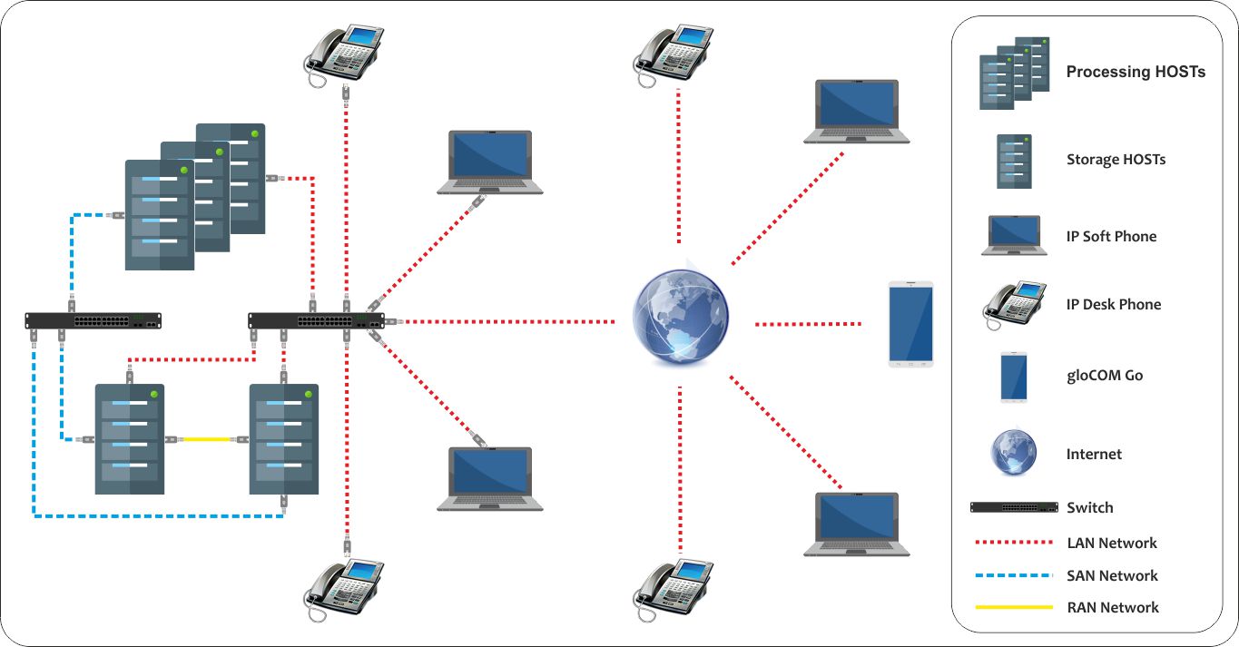
- LAN - Local Area Network used for SERVERware management traffic as well as for VPSs services.
- RAN - Replication Area Network is used for the storage mirroring. It is implemented as a direct connection between two storage hosts that constitute a fault-tolerant storage solution.
- SAN - Storage Area Network is used for storing traffic between storage and processing hosts.
- In the Hosts view, select the host to be placed in maintenance.
- Click the Maintenance button. A confirmation dialog appears.
- Click Yes.
- The State field of the host changes to MAINT (maintenance). The icon changes to indicate that the host is in maintenance.
- Perform any required task. When the host is ready to be re-enabled, click the Enable button to enable the host. The State field of the host changes to UP.
- In the Hosts view, select the host that you want to edit.
- Click the Edit button. The Edit Host dialog appears (see Add Host dialog).
- Edit the details as required.
- Click Save to save the changes.
- In the Host view, select the host to be removed.
- Click the Remove button. A confirmation dialog appears.
- Click Yes. The host disappears from the list.
-
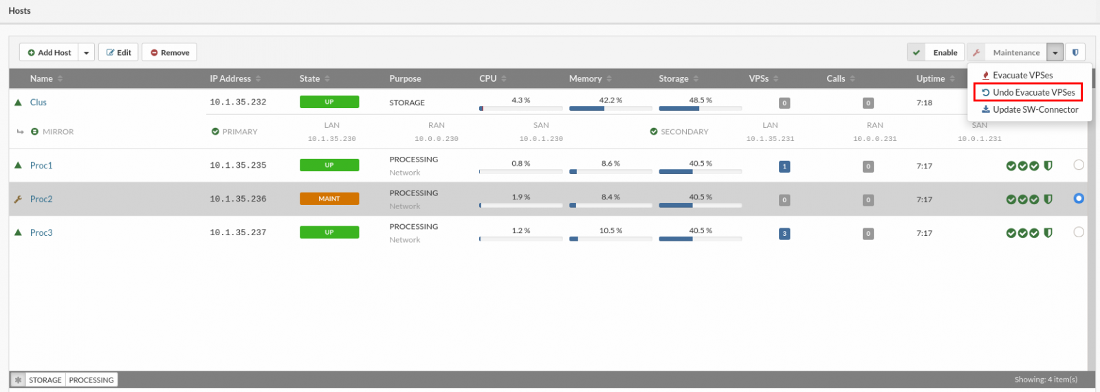
Example: If we have a processing host with VPSs and we need do some maintenance on the host update system, HDD, RAM, CPU, etc.. we can use Evacuate action the evacuate action will move all VPSs from the host to another host/host's, depending on the user selection, when maintenance work is finished and host back on-line Undo evacuate action can move VPSs back to our host in a state before the evacuate actions. The VPSs that have been moved/deleted between these actions will be ignored in Undo evacuate action.
-
To start undo evacuate process, select desired host from hosts view and in the upper right corrner dropdown select Undo evacuate action
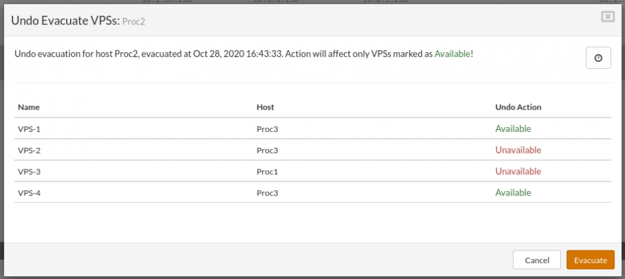
- If undo evacuate action is available for the selected host the popup will appear with the list of the available VPSs for the undo action.
-
VPS marked as Unavailable will not be affected by this action (these VPSs must be moved manually)
-
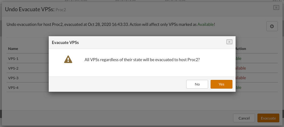
Confirm dialog is displayed before the action started. The evacuation process will cause some down-time to the VPSs the down-time depends on the hardware, VPSs size, etc.
-
After the confirmation, the evacuation process will start and can not be stopped until finished.
-
NOTE: During Undo evacuate process some hosts will show status Evacuating this is normal for Undo evacuate action.
-
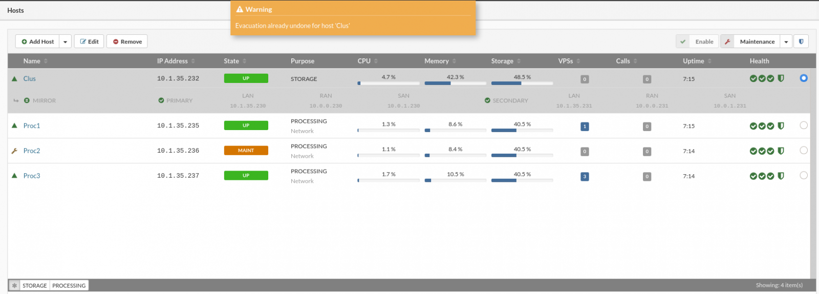
In case there is no Undo evacuate available for the selected host or the Undo evacuation has already been executed on the selected host, a warning message will be displayed.
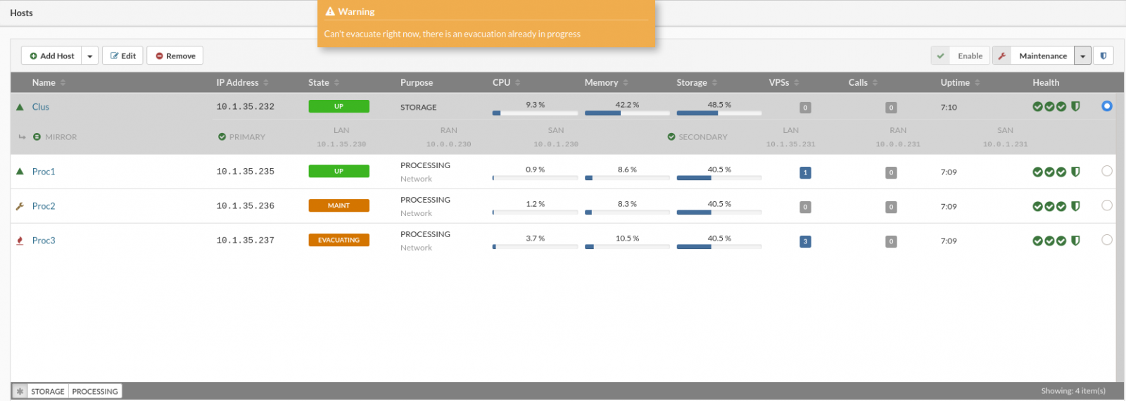
- Multiple evacuation actions can not start at the same time.
- A smal question mark near the host on the right side in a HOST wiev is an indication of new sw-conn update available.
- In the Host view, select the host which sw-connector has to be updated.
- Move the host into maintenance mode.
- Click the Update SW-Connector button.
- Open the System Logs view to track the progress of updating.
- When the update is complete, click the Enable button to enable the host.
- SERVICE
- SYSTEM
- OCI
- LXC
- KVM (supported from SERVERware version 4.5.0 and above)
- • 1
- • 2
- • 4
- • 6
- • 8
- • 10
- • 12
- • 14
- • 16
- • 18
- • 20
- • 24
- • 28
- • 32
- • 64
- • Unlimited
- • 100
- • 200
- • 500
- • 1000
- • Unlimited
- Default value for all VPSs will be 256MB
- Minimum value is 64MB
- Default value for all VPSs will be 128MB
- Minimum value is 64MB
- Go to the VPS menu and select create new VPS from the top menu
- Create a new VPS, a popup will appear, in the general tab select the OCI radio button to use OCi templates for VPS
- Select the OCI template from the dropdown
- Select VPS engine (LXC or KVM) and continue to create the VPS same as any other.
- Starting, Stopping and Restarting virtual servers,
- Changing virtual server ownership,
- Increasing virtual server storage, changing VPS engine (LXC or KVM)
- Cloning and migrating virtual servers,
- Restoring virtual servers.
- In the Virtual Private Servers view, select the VPS that you want to edit.
- If the VPS that you want to edit is not visible in the list, perform a search.
- Click the Edit button. The Edit VPS dialog appears with the disabled fields that cannot be changed.
- Edit the required details of enabled fields under the desired tab.
- Click the Save button. The details of the VPS are updated in the view.
- In the Virtual Private Servers view, select the VPS that you want to edit.
- If the VPS that you want to manage is not visible in the list, perform a search.
- Depending on action that you want to perform click either Start, Stop or Restart button.
- Monitor VPS state change in the VPS view.
- In the Virtual Private Servers view, select the VPS for which you need to change owner.
- If the VPS that you want to change is not visible in the list, perform a search.
- Click the Change Owner button.
- Change Owner dialog appears.
- Select a new owner from the list and click the Change button to change ownership of the VPS.
- Closing the browser tab will not terminate a session.
- This feature is enabled only for SERVERware administrators, not for Partition admins or VPS owners.
- Links (URLs) for the sessions are not sharable.
- TTY session will work even if the VPS doesn’t have the network interface defined.
- Stopping the VPS will close all the TTY sessions for the VPS.
- The TTY session timeout is 30 minutes of inactivity.
- Create the new VPS from the template ( SERVERware or OCi)
- Start the VPS
- On the bottom info panel select terminal TAB
- Press the “Open TTY” button to open the Console access to the VPS
- Perform various actions in the VPS over the TTY - Console
- In the Virtual Private Servers view, select the VPS that you want to move.
- If the VPS that you want to move is not visible in the list, perform a search.
- Click the Move VPS button.
- The Move VPS dialog appears.
- Select Host Change as Move Type.
- Select a destination host from the list and click the Move button to initiate move operation.
- Monitor task progress in the VPS view. The host column should show a new hostname for the moved VPS.
- In the Virtual Private Servers view, select the VPS that you want to move.
- If the VPS that you want to move is not visible in the list, perform a search.
- Click the Move VPS button.
- The Move VPS dialog appears.
- Select Partition Change as Move Type.
- Select a new Partition from the list and click the Move button to initiate move operation.
- Monitor task progress in the VPS view. The partition should show a new name for the moved VPS.
- In the Virtual Private Servers view, select the VPS that you want to clone.
- If the VPS that you want to clone is not visible in the list, perform a search.
- Click the Clone VPS button.
- The Clone VPS dialog appears.
- Enter a description and a new name for a VPS and click the Clone button.
- Monitor task progress in the VPS view. The name column should show a new name for the cloned VPS.
- To finish configuration of VPS click Edit and then select Networking tab.
- On the Networking tab select the logical subnet to which you want to connect the VPS.
- Enter an IP Address belonging to the selected logical subnet.
- Click the check box “Include in Geo-Redundancy” and select the site if needed.
- Then click the Clone button to start the clone VPS process.
- In the VPSs view, select VPS that needs to be removed.
- Click the Remove button. A confirmation dialog appears.
- Click Yes. VPS disappears from the list.
-
Go to the VPS menu and click on the Removed VPSs icon

-
Select the VPS and click Restore
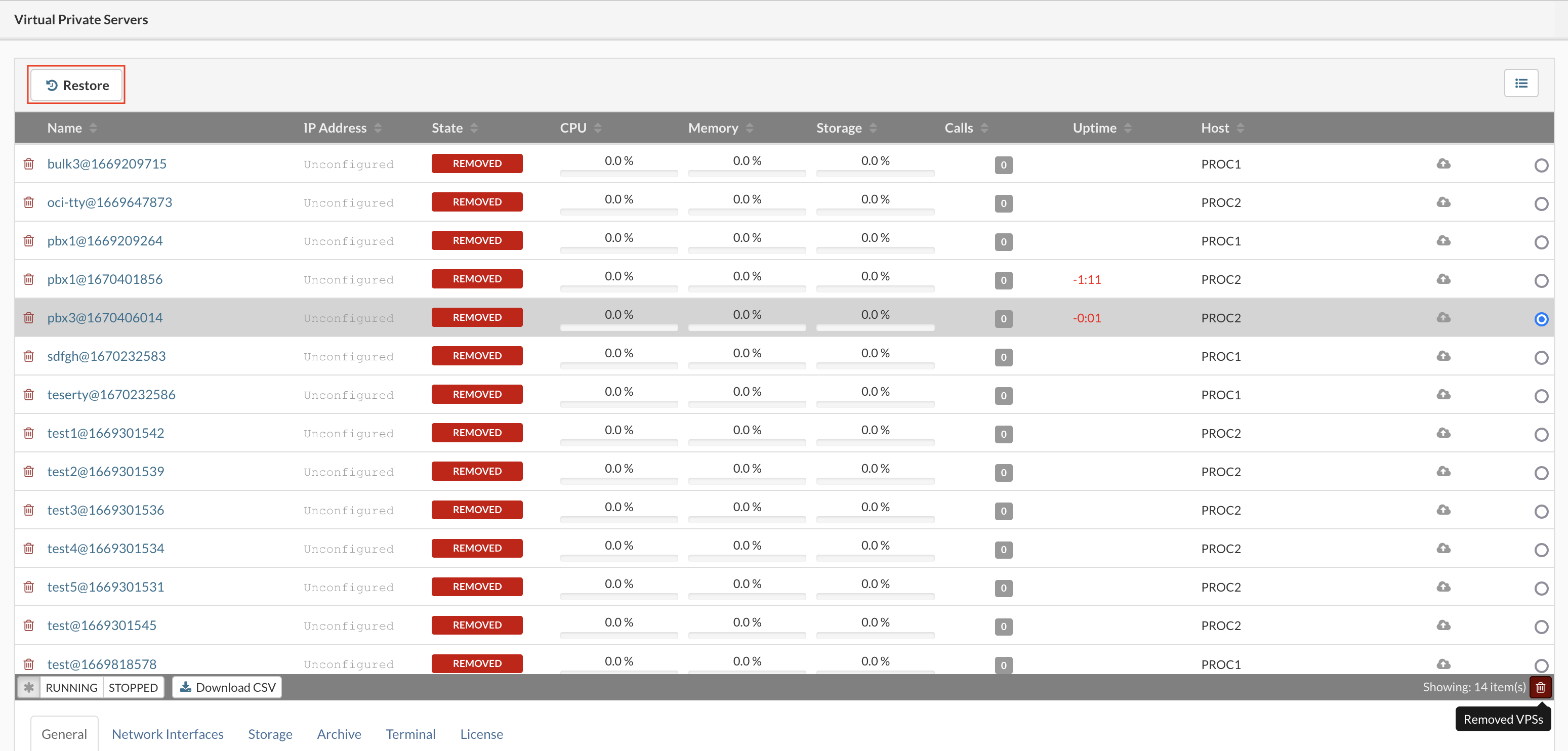
-
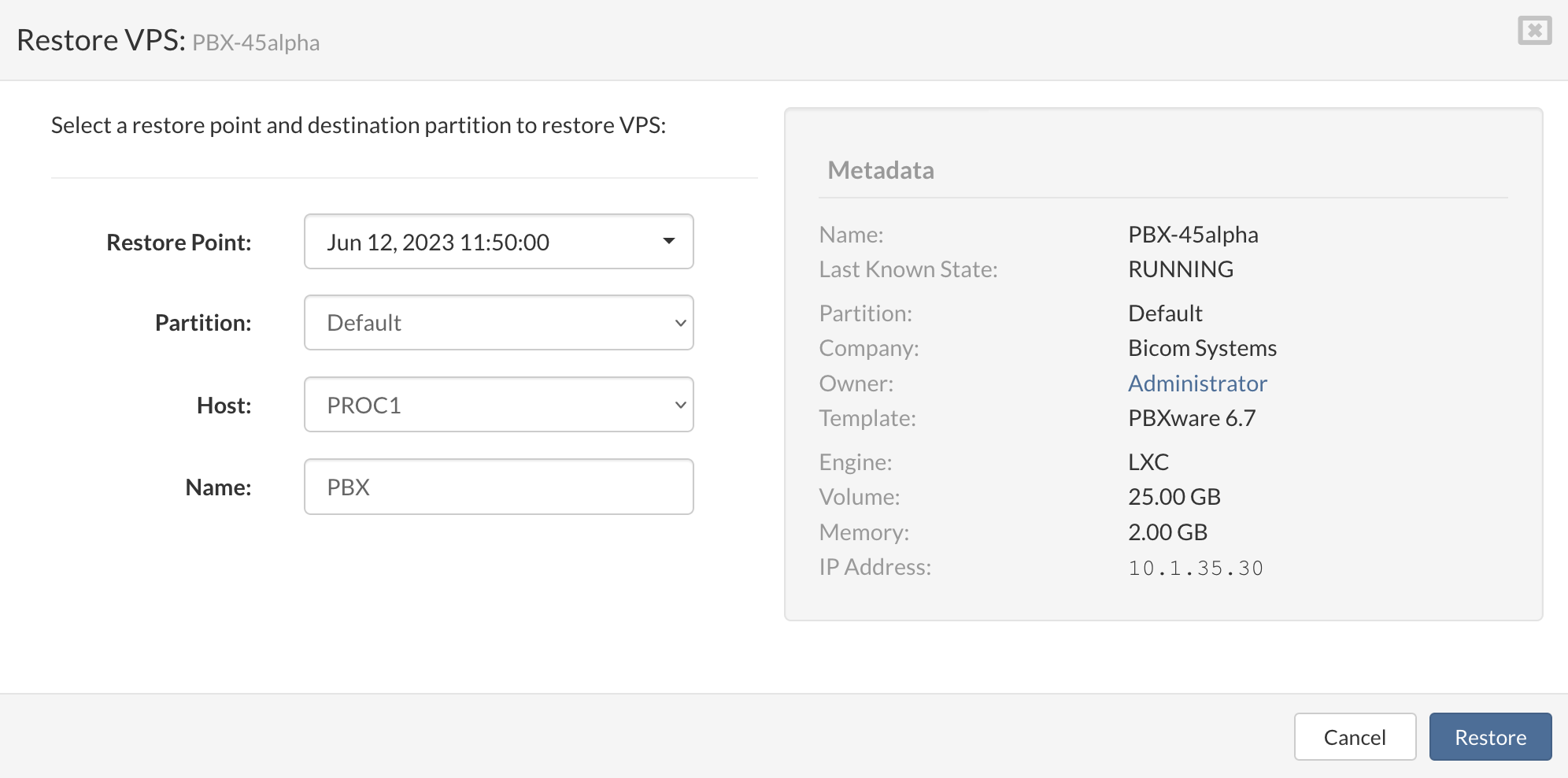
Pop-up menu will appear, then select Restore Point, Partition, Host, and Name of the VPS
-
Click the Restore button to start the restore VPS process.
- CPU Usage (Utilization/IO Wait)
- CPU Load
- Memory Usage
- Concurrent Calls
- Pool Usage
- Network Bandwidth Utilization
- In the Statistics view select a view category. Select either Host Charts or VPS Charts depending on which statistics charts you want to show.
- Select which data series you want to show Average or Maximum.
- Select metrics that you want to show on the chart view pane.
- Select a period for which you want to show the performance charts.
- In the Schedule view, select the backup job to be removed.
- Click the Remove button. A confirmation dialog appears.
- Click Yes. The backup job disappears from the list.
- Incremental replications
- Keep multiple replication cycles in time at GRS
- Takeover from multiple points in time
- Data synchronization separated from active services on takeover site and not affecting active services
- Add one or multiple GRS
- Monitor each GRS status
- Monitor recent replications
- Flexibility in combinations for replicating between sites
- The site can replicate to one or more destination sites
- One or more sites can replicate to one destination
- Different VPSs can be replicated to different remote sites
- Connect to remote GRS specifying its IP address and secret API key
- Control bandwidth and storage IO utilized by GRS
- Select SERVERware partitions and VPSs to be replicated
- Select the replication cycle, the minimum is one minute
- Specify how many recovery points to keep
- Control bandwidth and storage IO utilized by GRS
- Specify Alternate IP of VPS, (IP to be used after takeover on remote site if different)
- Monitor progress and completion status of each cycle and VPS replicated in that cycle
- Multiple sites can be replicated
- Select origin site and VPS to takeover
- Choose latest or older recovery point, in case most recent, contains unwanted data
- Choose destination partition
- Choose destination host
- Save Template for fast takeover in case of disaster
- Using the CLI administration interface, the administrator can allocate and control multiple sites on single GRS
- Limit storage
- Limit bandwidth
- Manage access control list
- Name The name of the Geo-Redundancy Server.
- IP Address Enter the IP Address of the Geo-Redundancy Server (If the Geo-Redundancy Server data-set is created on NETSTOR in mirror or cluster edition of SERVERware, floating IP should be used).
- API key Enter the API key for the Geo-Redundancy Server site.
- Send an email notification Select which notifications you want to be sent on administrator email.
- When Geo-Redundancy Server goes offline - This notification will be triggered when Geo-Redundancy Server is offline (network issue, hardware issue, etc..).
- If Replication fails - This notification will be triggered if the replication process is interrupted.
- If Replication completes with errors - Replication process is completed with errors for example when Geo-Redundancy Server site quota is reached or missing IP address.
- API Port Enter the API port for the remote site if needed (8282 default).
- Data Port Enter the port for data transfer if needed (7788 default).
- Max Bandwith Limit the Geo-Redundancy transfer rate to suit your network preferences and infrastructure.
- 1MB/s
- 5MB/s
- 10MB/s
- 20MB/s
- 30MB/s
- 40MB/s
- 50MB/s
- 75MB/s
- Unlimited
- Name Name of Replication site
- Replication Details
- Status Enabled or disabled replication
- Frequency How often Replication Cycle occurs (this is defined in Replication Config)
- Last run Time when last run of replication cycle occurred
- Next run Time when next run of replication cycle is scheduled
- Server Details
- Status Status of Repication server can be Online or Offline
- IP address Ip addres of Geo-Redundancy Server
- API port API port used to connect on Geo-Redundancy Server
- Bandwidth Bandwidth usage by Geo-Redundancy Server
- Storage usage Storage usage and quota of Geo-Redundancy Server
- Replication Enable or disable replication
- Replication Cycle Select the desired value in minutes from the predefined drop-down list (Replication Cycle is the time frame between replications)
- Recovery points to keep Enter the number of recovery points to keep (Bigger the number of the recovery points the more space on Geo-Redundancy Server will be used)
-
From the dropdown select the partition you want to replicate on another location when selected a list of VPSs from the selected partition will be displayed.
-
Check the boxes next to the VPSs you wish to replicate or Check the box next to the partition name to select/deselect all.
-
Alternate Local IP address - Define an alternative IP address for the VPS to use after the takeover. (Address used must be available in the remote SERVERware IP address pool, and if PBXware service is used, it must have secondary IP address defined)
-
Alternate External IP Address - Define an alternative external IP address for the VPS to use after the takeover. (Address used must be available in the remote SERVERware IP address pool, External IP Addresses enable the VPS to be available from a public network when NAT is used to forward its private IP address to a public IP address)
-
Press "Save and Apply" to finish setting up the replication.
- Start Time Time when the replication cycle is started.
- Duration Duration of the replication cycle.
- Data Transferred Amount of the data transferred in the cycle.
- Transfer rate Max transfer rate in cycle.
- Cycle ID Unique ID for the cycle.
- Details per VPS transferred in the selected cycle.
- Name The name of the Geo-Redundancy Server
- IP Address Enter the IP Address of the Geo-Redundancy Server (If Geo-Redundancy storage is located on NETSTOR in mirror or cluster edition of SERVERware, floating IP should be used)
- API key Enter the API key for the Geo-Redundancy Server site
- API Port Enter the API port for the remote site if needed (8282 default).
- Data Port Enter the port for data transfer if needed (7788 default).
- Max Bandwith Limit the Replication transfer rate to suit your network preferences and infrastructure (Other server-side limits may apply).
- 1MB/s
- 5MB/s
- 10MB/s
- 20MB/s
- 30MB/s
- 40MB/s
- 50MB/s
- 75MB/s
- Unlimited
- Recovery Point From the dropdown list select the desired recovery point
- Partition Select the partition for the restored VPS
- Host Select the processing host where the restored VPS will be placed
- Name Enter the name for the restored VPS
- To start a Bulk takeover action we need to make the list of VPSs for takeover first.
- First select Geo-Redundancy Server and replication site upper left corner, afterward select the upper-right drop-down menu and select Bulk takeover.
- New window will open with the possibility to create a bulk action list, start bulk operations, and save an operation as a template.
- Template Name: The name for the takeover template.
- Source Partition(s): Select the source partition of the VPS to recover.
- VPS: Select the VPS from the drop-down list.
- Recovery Point: select the recovery point for the VPS (NOTE: If the operation is saved as a template this will be automatically populated with the latest available point).
- Partition: select the destination partition for the VPS
- Host: Select the destination host for the VPS
- Name: select name for the VPS (This is automatically populated from metadata, and can be changed, duplicated names will not be allowed).
- Save this list as a template and run later Save Template (Templates can be modified later if needed in the saved templates window).
- Start bulk takeover action instantly Start.
- Create site monitor - This will open a new frame for creating a new site monitor (create an empty set of test to be executed and actions to trigger)
- Edit - Edit existing site monitor (site monitor has to be stopped prior to editing)
- Remove - Remove existing site monitor (site monitor has to be stopped prior to removing)
- Start - Start site monitor actions
- Stop - Stop the site monitor actions
-
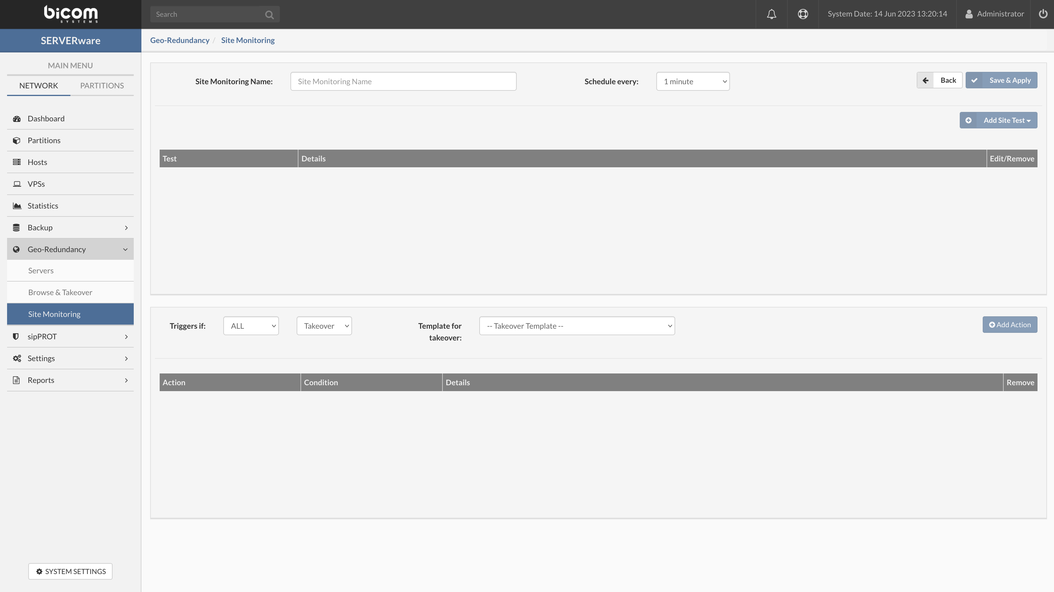
When Create site monitor button is pressed site monitor edit view will open.
-
Here we add tests to our new site monitor, first, we have to add a new name for our monitor.
- Site Monitoring Name: enter the name for the new site monitor, make sure to set the name in a few words explaining what site you are monitoring or similar for a better overview.
-
Then we will set the interval of our tests(all tests will execute in a set period for the selected site).
- Schedule every: Select the period from the predefined dropdown. this is the period in which all tests in this monitor will be repeated.
- Example: if the Schedule timer is set to 1 minute all tests added to this site monitor will be executed every minute(if the test can't finish in the selected period this period will be delayed until all tests are finished).
-
And we will save our monitor, so we can continue adding test cases.
- Save & apply: When we enter the site name and select schedule time we have to save this monitor to be able to add test and triggers.
-
Now we add our new test to the selected site monitor.
- Add Site Test: This will open a popup with the test design parameters.
- Add Site Test: This will open a popup with the test design parameters.
- ICMP test parameters
The ICMP test is the standard ICMP command set and additional success conditions. - Test successful example:
- Test failed example:
- HTTP test parameters
- TCP test parameters
- TCP Test example:
- UDP test parameters
- UDP Test example:
- MMonit integration
- Create actions to be triggered if conditions are met
- Add Action button : This will add action to the action list with a preselected option
- Trigers if: Two conditions available ALL and ANY and one action ALARM.
- ALL: Trigger alarm only when all tests fail for this site.
- ANY: Trigger alarm when any of the tests fail for this site.
- Alarm: Select action to trigger when conditions are met.''The Alarm will be displayed on the dashboard, an email notification will be sent to the administrator''
-
Simple plain data redundancy between site
-
Hosting data redundancy between sites
-
Case 1, SERVERware on primary and takeover site will be connected to Geo-Redundancy Server with admin API key. The administrator will have access to browse all data on the Geo-Redundancy Server and takeover from any site any replicated VPS to default or partition by choice.
-
Case 2, SERVERware on the primary site will be connected to the Geo-Redundancy Server with user API key and takeovers will be managed by the hosting provider. (Hosting provider will provide credentials and IP address for the GRS)
- - add -storage -quota [KMGT] -throttle [KMGT] -admin=true/false -allowedips ... "quoted description text"
- -allowed IPs specify quoted the comma ',' separated list of IPs or subnets in CIDR format
- - update -storage -quota [KMGT] -throttle [KMGT] -admin=true/false -allowedips ... "quoted description text"
- - list [id] List sites, showing unique id and other settings.
- - remove [-force] id Remove site by its unique id
-
- list [id] Show the list of all defined replications for this daemon.
-
- help Show help.
-
public_key { help } Output own rsa public key.
-
admin_key {set newkey} { help } Output or set current admin API key.
-
task { COMMAND | help}
-
- list [-l, -t backup] [id] List tasks, showing unique id and other settings.
-
-l - Limit list size (default is 10, 0 for unlimited)
-
-t - filter tasks of specific type backup,replication or srv_backup,srv_repl
-
id - id of task for detailed output
-
- cancel id Cancel task by its id
- Find out the name of the pool by typing:
- When we know the name of the zfs pool we can create a dataset for Replication storage we will use the name of the pool from the previous command "SYSTEM-e694" add trailing slash / and dataset name, in our case "GRS" so the command will look like this:
- Next, we need to create the mount point and boot parameters for the new dataset
- Create a directory and mount our newly created ZFS dataset.
- We should add this mount point to the "/etc/fstab" so the SERVERware mounts this dataset after reboot.
-
Reboot the processing host.
-
After the host, reboot log on and inspect dataset and mount point we have just created in ZFS
-
PBXware - in case you are running standalone PBXware installation on dedicated hardware.
-
SERVERware host - If you are running PBXware as a VPS in a SERVERware virtual environment, sipPROT should be installed on all SERVERware hosts.
- VOIP service downtime and unreachability
- The possibility of password stealing (SIP registration)
- start/stop sipPROT
In order to start, stop or check status of sipPROT daemon use following command: - In the Settings menu, select Networking view.
- Click Remove next to the logical subnet you want to remove. A confirmation dialog appears.
- Click Yes. Logical subnet disappears from the list.
- Name: Enter the new network name (limited to 15 characters).
- Type: From the dropdown select the type VIRTNETIPv4 for the network (there are two options for virtual networks "VIRTNETIPv4" for IPV4 and "VIRTNETIPV6" for IPV6)
- IP address: Enter the network address range
** Example for IPv4: 192.155.0.0 - Subnet Mask: Enter the subnet range for the selected network
** Example for IPv4: 255.255.0.0 - Gateway: 192.155.0.1 (The gateway address will be added to the CONTROLLER of the SERVERware and the CONTROLLER behave as a Gateway/router for the virtual networks)
- Name: Enter the new network name (limited to 15 characters).
- Type: From the dropdown select the VIRTNETIPv6 for the network (there are two options for virtual networks "VIRTNETIPv4" for IPV4 and "VIRTNETIPV6" for IPV6)
- Routing prefix: Enter the network routing prefix for your IPv6 network (SERVERware will auto-populate this field)
- Example for IPv6: fd:ce8c:54b5
- Subnet ID: Enter the subnet ID for the selected network
- Example for IPv6: 1
- Gateway: Enter default gateway (The gateway address will be added to the CONTROLLER of the SERVERware and the CONTROLLER behave as a Gateway/router for the virtual networks)
- Example for IPv6: fd:ce8c:54b5:1::1
-
VPS can change IP or network and still remain accessible via domain name with no additional configuration changes on DNS since SERVERware is authoritative for a given zone.
-
This can be used as a service discovery mechanism (SRV record) It simplifies DNS management for providers with multiple services since all they need to do is to forward requests to SERVERware
-
This gives us the opportunity to deploy multiple public DNS instances via the device provisioning feature in PBXware, and connect them in real-time with SERVERware that will eliminate caching issues of third-party resolvers.
- Press the add new zone button
- Type: From the dropdown select the role of server primary or secondary
- Add the name of your domain server1.mydomain.xzy in the field Name (this will be the resolve name for your DNS zone)
- In the Domain field from the dropdown select the Domain to limit the DNS record to the selected SERVERware domain (default selection will use all domains available on the SERVERware).
- The default port is 53 this is the default port for DNS (domain name server) lookup and should not be changed if otherwise not required from your network administrator.
- TTL (time to live) is a setting that tells the DNS resolver how long to cache a query before requesting a new one. The information gathered is then stored in the cache of the local resolver for the TTL before it reaches back out to collect new, updated details.
- Transfer From: This field should be populated with the IP address of the primary server in the DNS zone and will be enabled only if the type is set to secondary.
- Transfer to (ACL): Enter the IP addresses of the servers you wish to specify, the application allows servers to send DNS zone data to the secondary server specified.
- Press SAVE button, we have added our DNS zone successfully
- Open the terminal and issue the next command:
- Select Administrators menu.
- Select Remove from the dropdown menu next to the administrator account you want to remove. A confirmation dialog appears.
- Click Yes. Administrator account disappears from the list.
- In the Administrators view, select Downgrade from the dropdown menu next to the administrator you want to demote. A confirmation dialog appears.
- Click Yes. Administrator disappears from the list and appears in the list of Partition Users.
- In the Partition Users view, select Remove User from the dropdown menu next to the user you want to remove. A confirmation dialog appears.
- Click Yes. The user disappears from the list.
- In the Partition Users view, select Upgrade from the dropdown menu next to the user you want to promote. A confirmation dialog appears.
- Click Yes. User disappears from the list and appears in the list of Administrators.
- Login Lockout enable/disable the feature
- Max. Failed Attempt maximum number of fail attempts in a given period before the SERVERware will block user account.
- Retry Time Period period in which the fail attempt happened before is blocked. The available selection is 1min, 5min, 10min, 30 min, and 60min.
- Block Time Period period in which the restriced user will have denied access
- IP Address or Subnet To block access for the specific IP address, in the input field type the address you need to block and press the + Add button.
- To remove the specific address from the blocked list of addresses press the X mark button next to the blocked IP address in the list.
- IP Address or Subnet To grant access for the specific IP address, in the input field type the address you need to grant access for and press the + Add button.
- To remove the specific address from the granted list of addresses press the X mark button next to the granted IP address in the list.
- Configure the number of maximum concurrent sessions. When enabled, attempts to connect beyond the maximum will be rejected. For example, if the session limit is 3, only 3 users can be connected simultaneously. Every next user login attempt will be rejected.
- Select Role & Permissions view.
- Select Remove Role from the dropdown menu next to the role you want to remove. A confirmation dialog appears.
- Click Yes. Role disappears from the list.
- Select Service Pools view.
- Click Remove Service Pool next to the service pool you want to remove. A confirmation dialog appears.
- Click Yes. Service pool disappears from the list.
- In the Alarms view, select Remove Alarm from the dropdown menu next to the alarm configuration you want to remove. A confirmation dialog appears.
- Click Yes. Alarm disappears from the list.
- In the Flavors view, click Add Flavor. Add Flavor dialog appears.
- Enter Name, select CPU Priority, CPU limit, amount of Memory, Storage, Bandwith, and IOPS limit than click Create to create a new flavor.
- In the Flavors view, select Remove Flavor from the dropdown menu next to the flavor you want to remove. A confirmation dialog appears.
- Click Yes. Flavor disappears from the list.
- Registry: select one of the two options
Docker Hub for images from public repo docker hub or custom for local/private repository. - Image: enter the path to the OCI image as required per place holder eg. library/mysql
- Tag: enter the version of the required OCI image or enter the latest for the latest available image.
- Description: enter the description/comment for the OCI image.
- In the Host view, select the host which sw-connector has to be updated.
- Move the host into maintenance mode.
- Click the Update SW-Connector button.
- Open the System Logs view to track the progress of updating.
- When the update is complete, click the Enable button to enable the host.
Storage can be extended by adding more disks which are set up in a redundant array (RAID 10), with two redundant servers connected in real time mirror (Mirror/Cluster Edition). In such setup disk failure does not interrupt the storage service. There is no practical storage size limit in the software, it is only limited by hardware specifications, such as largest disks available on the market (in terms of capacity), and number of disks that can be connected to servers, RAM memory, etc…
SERVERware storage employs the end-to-end checksum to detect and correct silent data corruption which means that storage will use this checksum to determine which copy is correct in this redundant disk array. This provides correct data to the VPSes, and repairs the damaged copy if it becomes damaged.
Press to expand (It is important to discern different editions of the SERVERware)
¶ Structure and requirements
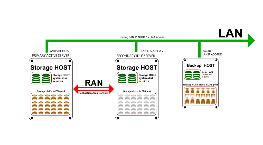
Except for Standalone edition, SERVERware will connect disks from two storage servers in a single storage pool (named NETSTOR). This is done by employing the ZFS as file system and volume manager, and the iSCSI protocol. Size of the storage is limited only by physical limitations. Connecting disks into storage requires dedicated physical network link between Active and Passive storage server with bandwidth of 1Gb/s minimum. This is called the RAN - Replication Area Network. Latency is absolutely critical here and for that reason direct cable connection is required between the servers without other network nodes in between (switches, routers etc..). One of the servers is primary and it is servicing storage to processing hosts (Cluster Edition). Each local disk on primary server is in mirror pair with equal or approximate size disk on second server. In such configuration disk from second server is accessed via iSCSI exported to RAN. In case of primary server failure, second server is able to takeover and continue the service.
¶ VPSes
For each VPS, SERVERware will create a ZFS volume, each volume is formatted to different file system, usually ext4. In case of Cluster Edition these volumes are exported to SAN (Storage Area Network) to corresponding processing host. Processing host will attach volumes assigned and accessible by it and then run the VPSs.
SAN requirements dictate that servers must have 1Gb/s port minimum per server and a switch to connect storage and processing hosts. To have minimum latency between servers it is recommended to keep this configuration as simple as possible. For failover capability, storage requires floating IP address on SAN, which is an IP that will move from primary to secondary storage server in case of primary server failover. For this to work one must make sure that this will be supported by switch, if such security settings exist (depending on model).
To increase the reliability of setup where processing hosts are used, SERVERware supports bonding of network interfaces. It is possible to have redundant SAN with two redundant switches. This requires two ports per server to be bonded in SAN.
Same is possible for RAN and LAN networks, but SAN is the most critical component and it is recommended to make it redundant before others.
Setup of storage configuration is automatic and everything is done via Setup Wizard. In order for this to be automated as such, it requires complete topology in place, servers installed, and networks configured. Of course, one must have correct information about these networks to make this happen. In short, one will have to select ports used for LAN, SAN and RAN and floating IP address will need to be chosen, including location of second storage server.
¶ Scalability and Repair/Maintenance
Scalability of storage is limited by the capacity of RAN and SAN networks and number and size of disks. It is simple enough to scale the storage by adding more disks in pairs, and configuring iSCSI targets depending on the edition.
For more information on how to scale the storage pool, please refer to our documentation manuals:
¶ TO LINK MANUALS FOR EXPANDING POOLS
No resource is unlimited in terms of storage, CPU, network and memory available. With that said, special attention should be paid to management and commitment of these resources.
Following limits must be observerd for storage:
Space limitations should be considered as ratio between actual usage and allocation. Not all VPSs will use the whole allocated storage so there is a space for overcommitment of available storage, but keep in mind that they all have potential to reach full usage and demand storage to extend.
How much can be overcommited depends on specific case and can not be generally predicted. Usage growth should be constantly monitored to be able to react on time. Careful planning of storage that will be required in future, and scalability plan and procedures is what will resolve potential issues with space limitations.
As more VPSes are added, or there is an increase in usage, there will be more demand on storage. To prevent potential problems, SERVERware monitors IO load of the storage and information is displayed on the dashboard. As a general rule, this load should never reach 10%. If this limit is reached, options to alleviate this would be to create new cluster for offloading the VPSs, or update of hardware with improved performance.
Bandwidth and latency limitations apply to SAN and RAN network but there is special case that should be observed when planning and deploying VPSes. Each VPS's IO bandwidth can be limited, and this option should be used appropriately, with same considerations as space overcommitment.
Not all VPSes will use the IO up to the limit all the time, but there is always a possibility for that to happen. For VPSes that have unlimited IO set, there is a potential problem where those VPSes utilize 100% of SAN/RAN resources and that way affect the functionality and performance of all other VPSes, causing a series of issues. In such cases, to alleviate those problems either upgrade the network infrastructure or create more clusters to offload affected VPSes. Of course, this needs careful planning prior to deployment.
Performance of networks and disks can be different, they can outperform each other on multiple occasions, so when troubleshooting, it's crucial to know where the bottleneck is, in order to know how to handle it.
¶ Deployment Guide for Mirror Edition
The following guide describes minimal and recommended hardware requirements as well as procedures for a successful deployment of SERVERware 4.2 - Mirror Edition.
¶ Hardware Requirements
¶ Server requirements for Storage/Controller
Press to expand (2 x server with the following)
| HARDWARE | MINIMUM SYSTEM REQUIREMENTS | RECOMMENDED SYSTEM REQUIREMENTS |
|---|---|---|
| CPU | 2.0 GHz Quad-Core Intel Processor with 8MB Cache | 2.4 GHz Quad-Core Intel Xeon Processor with 12MB Cache |
| RAM | 16GB | 32GB |
| Ethernet | 8 x 1Gb/s network interfaces | 2 x1Gb/s + 4 x10Gb/s network interfaces |
| Disk | 1 x 64GB Solid-State Drive (for system), 2 x 500GB Solid-State Drive (for storage) | 1 x 64GB Solid-State Drive (for system), 4 x 250GB Solid-State Drive (for storage) |
¶ Server requirements for Backup Hosts
Press to expand (If added, Backup Hosts should have the following)
| HARDWARE | MINIMUM SYSTEM REQUIREMENTS | RECOMMENDED SYSTEM REQUIREMENTS |
|---|---|---|
| CPU | 2.0 GHz Quad-Core Intel Processor with 8MB Cache | 2.4 GHz Quad-Core Intel Xeon Processor with 12MB Cache |
| RAM | 16GB | 32GB |
| Ethernet | 1 network interface | 3 or more, network interfaces |
| Disk | 1 x 1TB Hard Disk Drive (for system and backup) | 1 x 64GB Solid-State Drive (for system), 6 x 1TB Hard Disk Drive (for backup) (RAID10) |
To add Processing Hosts, SERVERware 4.2 license must be upgraded to Cluster Edition and at least 2 Processing Hosts added to effectively relieve Storage/Controller.
Upgrade to Cluster Edition increases the number of required network interfaces to 3 on every server in the cluster.
Software RAID (including motherboard) implementations are not supported and could cause potential problems that Bicom Systems would not be able to support.
¶ KVMoIP (Keyboard, Video, Mouse over IP) remote access to each server
¶ SERVERware installation media is required in one of the following forms
¶ Deployment Guide
SERVERware 4.2 Mirror Edition topology is shown on the following image:
¶ Network setup
How-to instructions regarding network setup are available on the following page:
¶ Disk setup
Because of ZFS, hardware RAID is not required, but if there is RAID controller present and you want to use it, battery and write cache are a must. Any hardware RAID without battery backup and write cache enabled, can't be supported. Fake RAID is not supported, should not be used and must be turned off if supported by motherboard (Fake RAID is essentially software RAID provided by the BIOS on the motherboard).
Lets say we have two disks for storage per server (disks must be identical).
Currently, setup wizard will form the following pool:
¶ Creating USB installation media
USB images and instructions are available on the following how-to page:
¶ Installation wizard steps
The System Installation Wizard has been enhanced to provide users with the ability to create ZFS pools on OS disks during the installation process. This feature streamlines the setup of ZFS pools, optimizing system performance and storage management.
Boot target machine from the USB installation media. The following welcome screen appears.
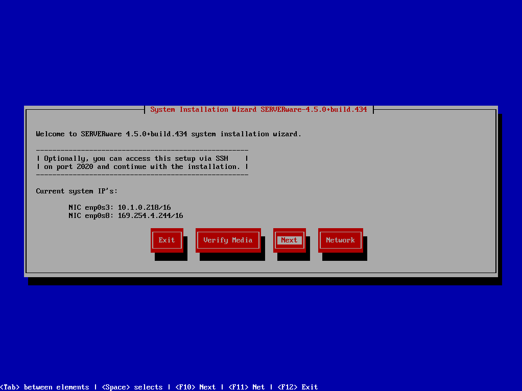
If the live system was able to pickup IP address from DHCP server, it will show so on this screen. You can then access the system remotely via ssh on port 2020 with username 'root' and password 'bicomsystems' and continue installation. There are several options offered on the welcome screen:
¶ Step 1: Select the type of installation you want to install, Storage/Controller or Host (Backup).
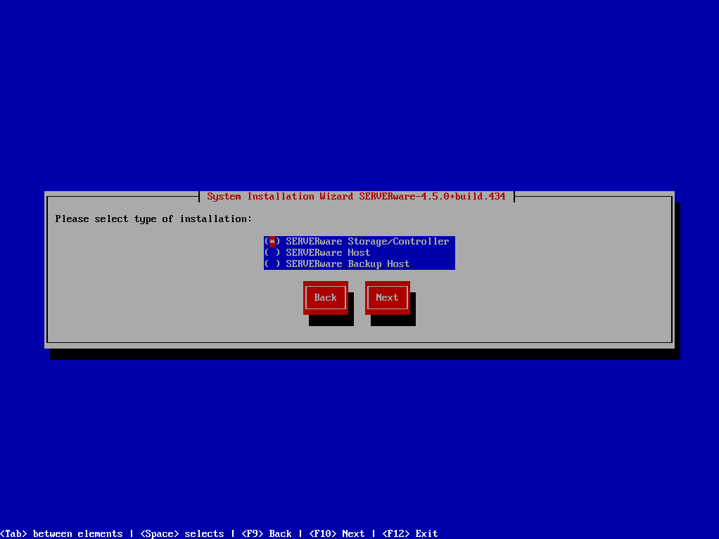
Storage/Controller is the network storage for VPSs on the SERVERware network. Processing Host (available in Cluster Edition) is computation resource that will attach and execute VPSs from storage via SAN (Storage Area Network).
¶ Step 2: Installation wizard will proceed to check for available disks, the wizard will identify available disks for the SERVERware operating system. It will then suggest suitable ZFS pool configurations based on the detected number of disks.
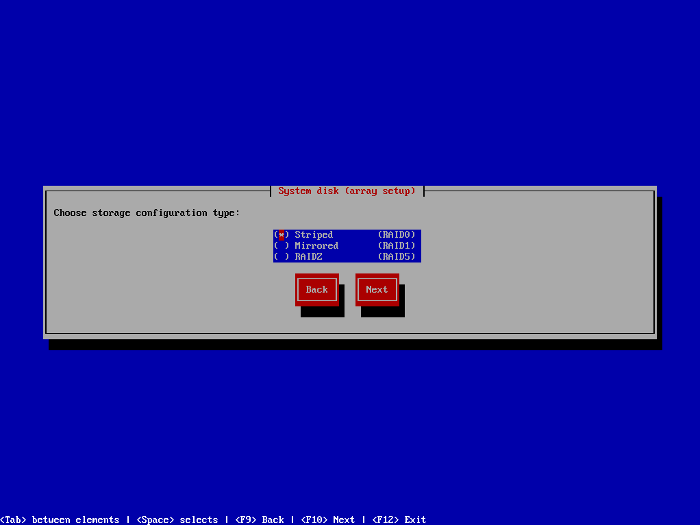
Users will have the following options to choose from:
User will be presented with the number of detected disks and the corresponding available options for creating the system pool. They can then select the desired ZFS pool configuration based on their requirements. The wizard will guide users through the process, making it simple and intuitive.
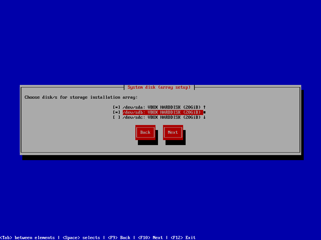
¶ Step 3: Select physical disk for "SYSTEM" installation. Volume for storage "NETSTOR" will be automatically created from disk's that are not selected in this step
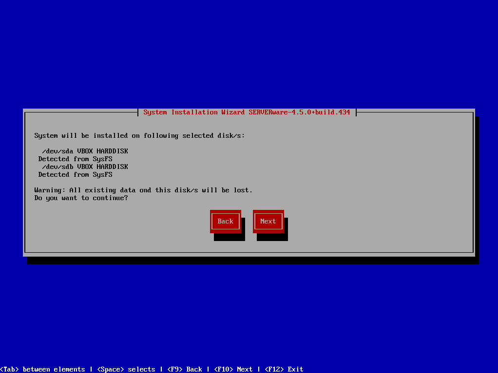
¶ Step 4: Confirmation dialog appears
¶ Step 5: Configure network dialog appears
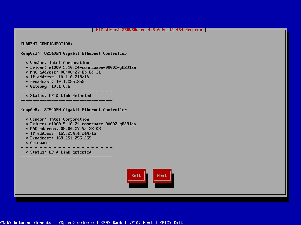
Click Next to continue and then chose one of the options to configure network interface.
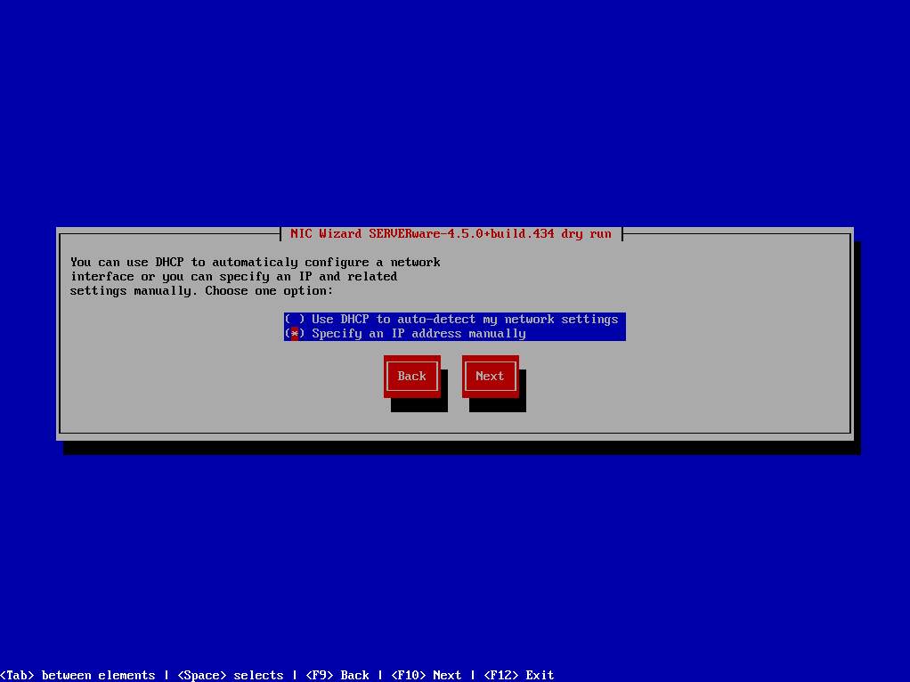
After finishing network configuration, click Next to start installation.
¶ Step 6: Installation wizard will now proceed with installation of SERVERware operating system.
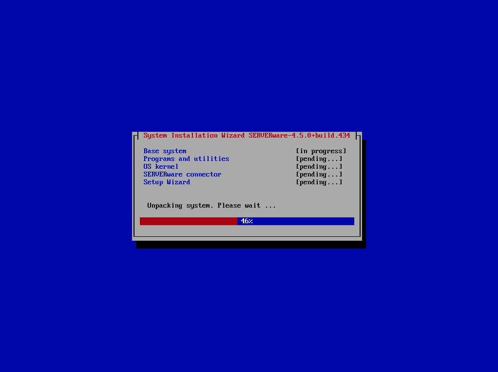
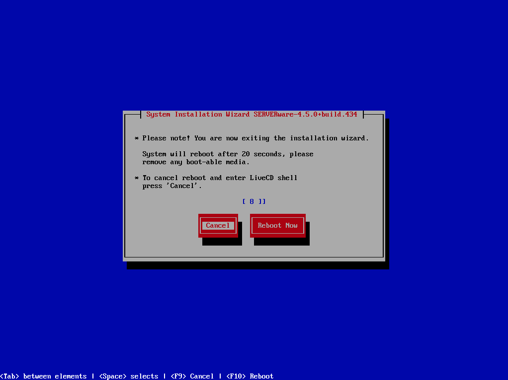
After finishing finishing installation. Wizard will initiate reboot.
¶ Step 7:
Redo installation steps for the second (mirrored) machine.
¶ VLAN Tagging on host and VPS interfaces
SERVERware features easy configuration of VLAN tagging, so that server can reach the internet or some specific networks.Some countries like the South African Republic, Australia, or countries in South America have VLAN tagging as a standard in their network environments. Without the tagging, services are not able to reach the internet or some specific networks. When server have single physical link for the LAN, access to both local and public network is possible using VLAN tagging. To create VLAN on SERVERware we need to complete install wizard using guidelines from ""Installation wizard steps"" section.
Run netsetup command in terminal and delete br0 interface. Now we have only one physical interface and next step is to create two or more VLANs.
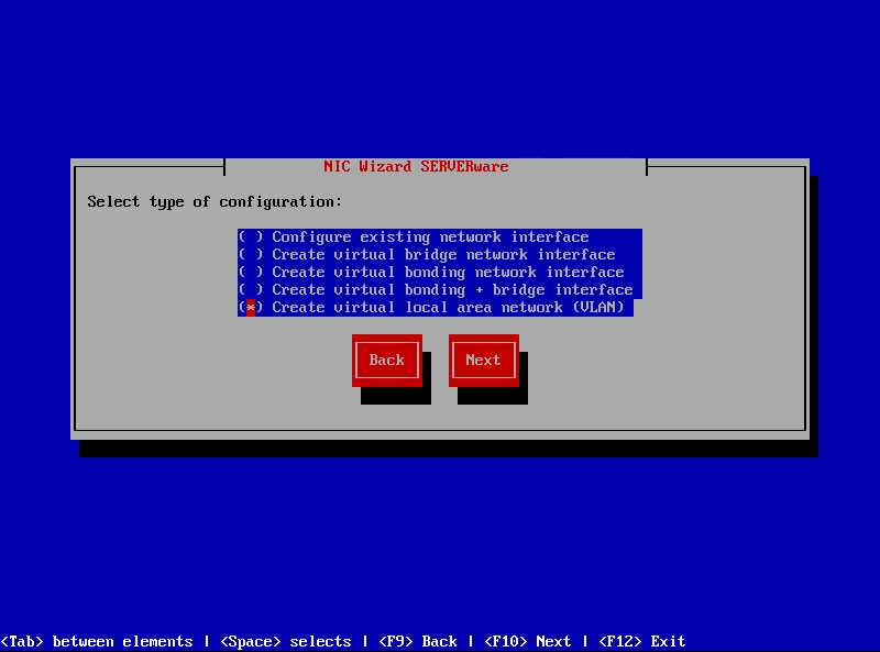
¶ Step 1: Run "netsetup" command and select ''Create virtual local area network (VLAN)'' and press ''Next''
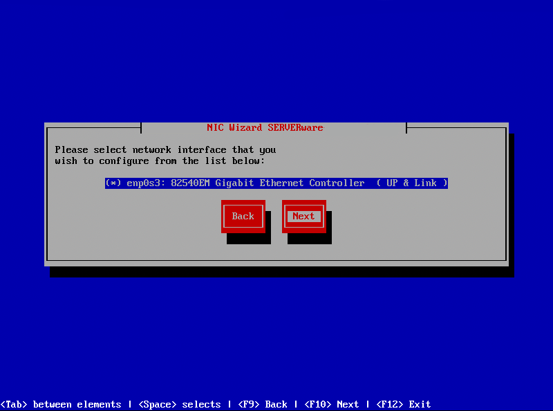
¶ Step 2: Select network interface and click ''Next''
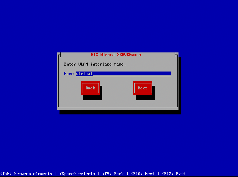
¶ Step 3: Follow three next steps to configure IP address of new VLAN interface. One of last steps will be to enter VLAN interface name. For name to be valid you should use min 3 and up to 20 alphanumeric characters without spaces. Also it is not possible to create VLANs with same ID.
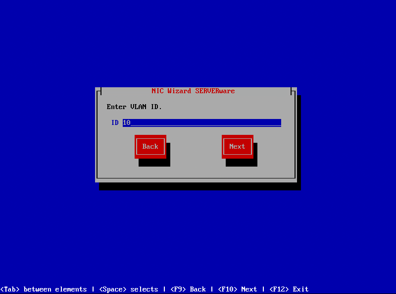
¶ Step 4: Enter VLAN ID. For VLAN ID use numbers in range between 2 and 4096. Numbers 0, 1, 1002-1005 and 4096 are reserved and therefore also can't be used
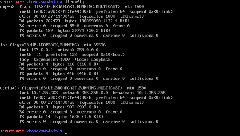
¶ Step 5: Complete NIC Wizard and run ''ifconfig'' to confirm VLAN interface is present with assigned IP address. If necessary you can use virtual interface to create bridge interface or another virtual interface. Al this can be done using ''netsetup'' NIC Wizard
¶ Setup wizard steps
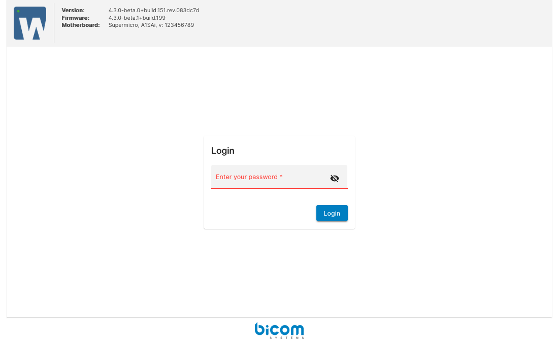
Open your browser and enter LAN IP you configured upon installation. After confirming self signed certificate, SERVERware setup wizard login screen appears. Enter administration password which is by default serverware.
¶ Step 1: After successful login, SERVERware EULA appears.
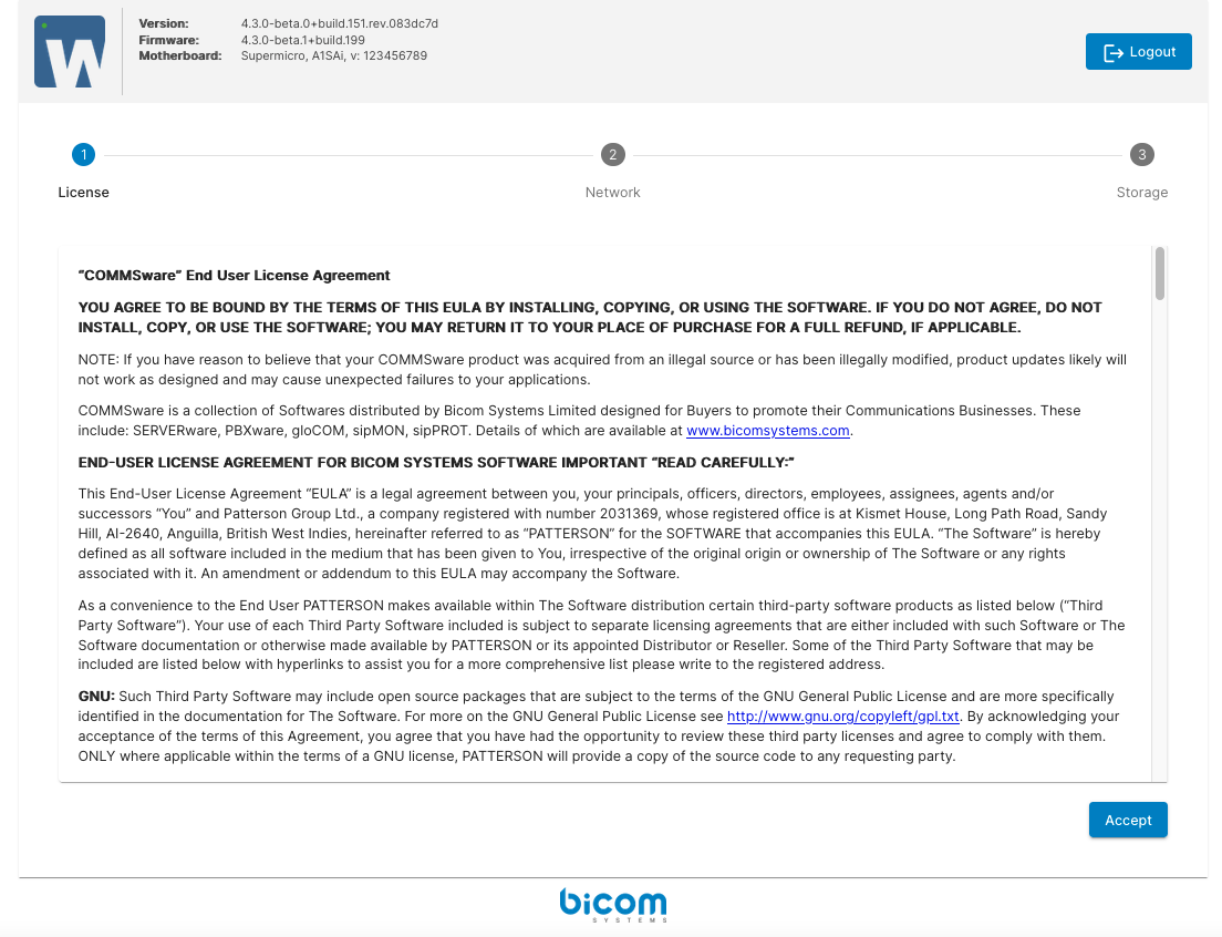
Acceptance of the EULA leads to the next step.
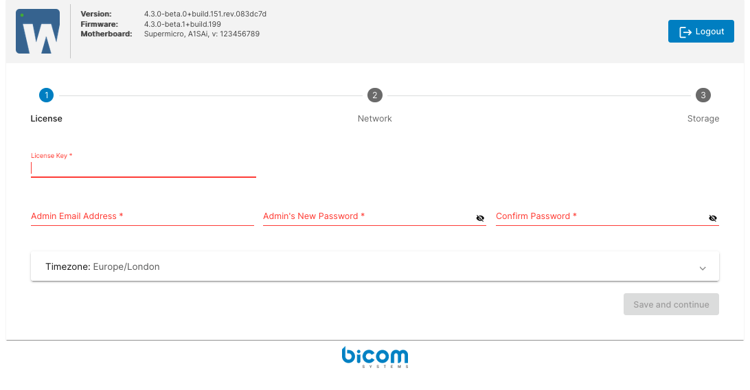
¶ Step 2: Enter your license number, administrator's email, set new administrator's SERVERware GUI password. This password will also apply to shell root account. Select your time zone and click ''next'' to continue
¶ Step 3: This step will offer you to configure LAN and mirror RAN network. LAN is a local network for SERVERware management and service provision. RAN is a network dedicated to real-time mirroring of two servers.
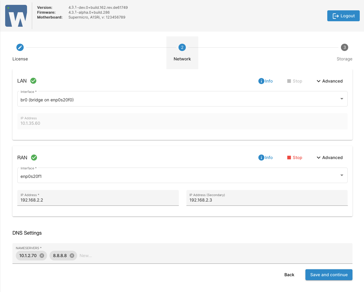
The setup wizard will suggest default configuration for the network interfaces. The machines must be on the same LAN network and the same RAN network. Modify network configuration if needed and click Next to proceed to the next step.
¶ Step 4: Choose the name for the server if you don't like the one generated by the SERVERware (it must be valid per hostname constraints).
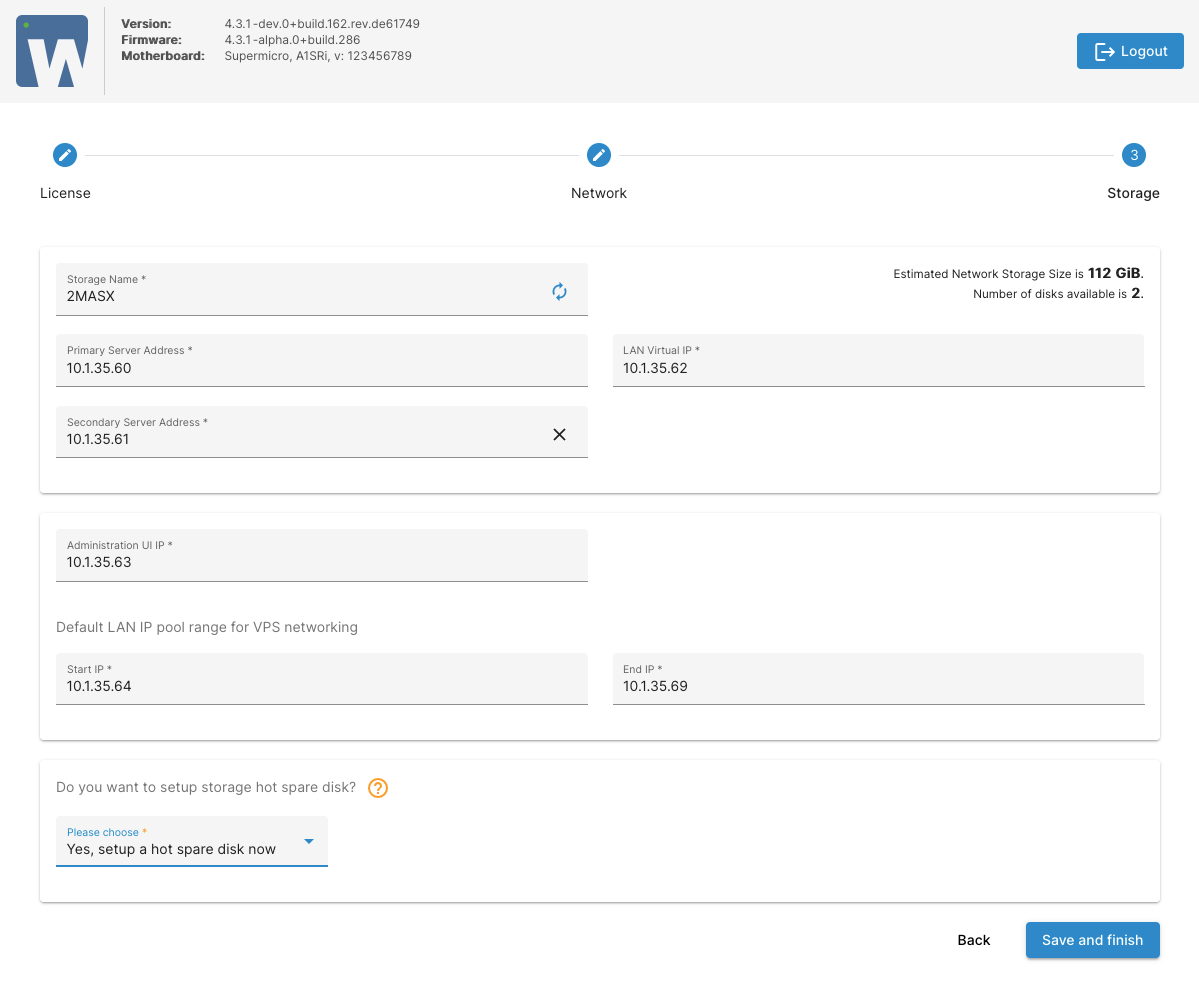
Select from the list or enter the LAN IP address of the second (mirrored) machine. Purpose of mirrored setup is to provide storage redundancy, so it will need a few more configuration parameters. LAN Virtual IP is a floating IP address for accessing mirrored storage server. Administration UI IP address will be used for CONTROLLER VPS (GUI).
CONTROLLER VPS is set up automatically on the storage server, and its purpose is to provide administrative managing web console as well as to control and monitor SERVERware hosts and VPSs.
Once you click Finish button, the wizard will initialize and setup the network storage. When complete, setup will present the summary info.
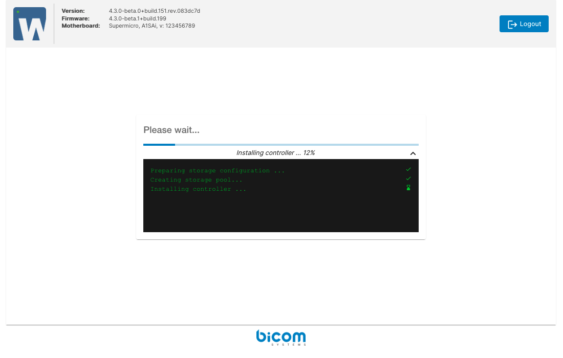
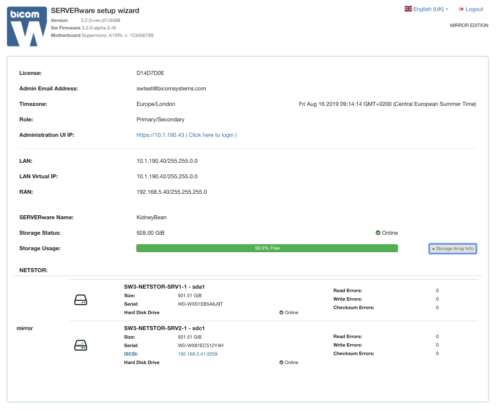
Wait a few seconds for CONTROLLER to start and click on the Controller Web Console link to start using SERVERware and creating VPSs.
¶ SERVERware Architecture
A SERVERware environment consists of:
SERVERware network topology is shown on the following image:
¶ SERVERware resources
The components of the SERVERware environment fall into two categories: physical resources, and logical resources. Physical resources are physical objects
such as storage and host servers. Logical resources are nonphysical groupings and processes, such as domains, logical subnets, and virtual server templates.
¶ Accessing the Web Control Panel
¶ Logging in to the Web Control Panel (Administration UI)
Log in to the SERVERware Web Control Panel directly from your web browser.
Enter IP Address of SERVERware Web Control Panel into the web browser to access the login screen.
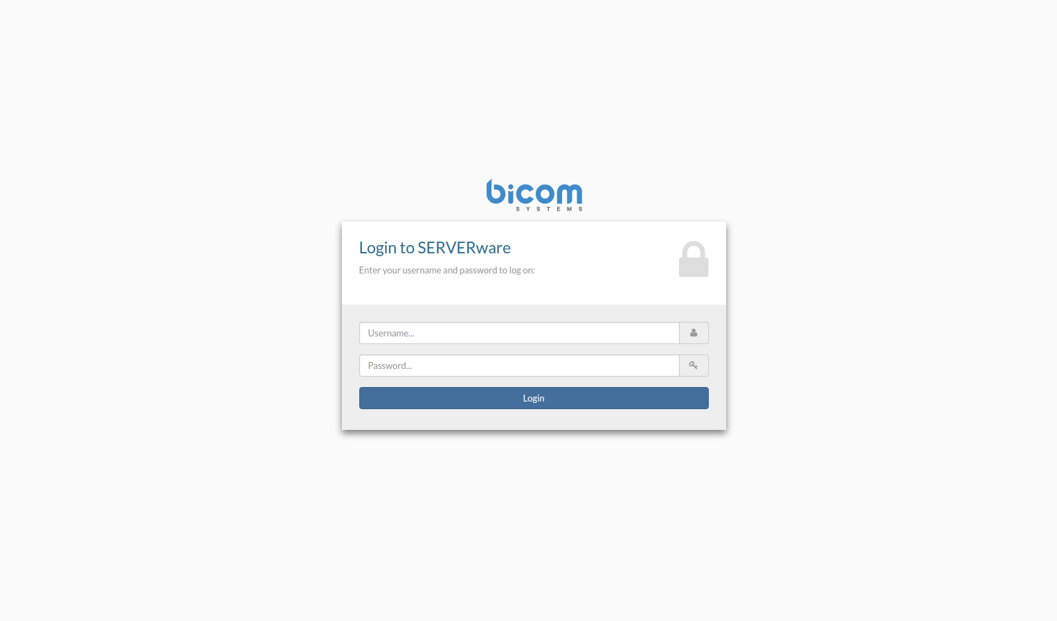
Enter your Username and Password.
Press the "Enter" or click "Login". SERVERware Dashboard appears.
¶ Logging out of the Web Control Panel
At the title bar of the Web Control Panel, click Logout.

You will be logged out and the Web Control Panel login screen displays.
¶ Enable 2FA for SERVERware
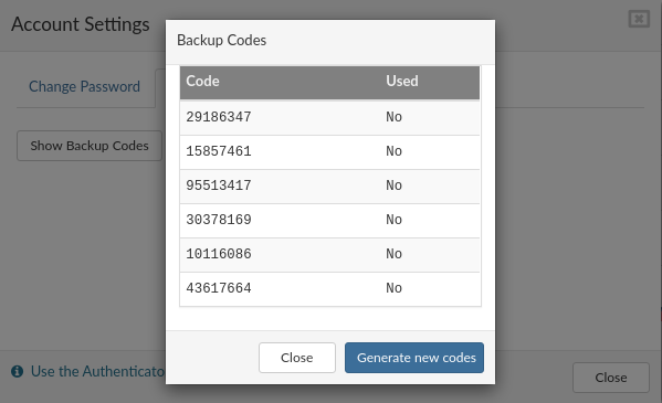
If your Authenticator App is not working or unavailable for some reason, you can use '''Backup Codes'''. Click on '''Show Backup Codes''' to view available codes. A new popup will appear with a list of codes and their status (used or not). One code can be used only once, if you don't have available codes you can generate new codes by clicking on the '''Generate new codes''' button.

¶ Network
¶ Dashboard
SERVERware network dashboard is a visual display of the most important performance
indicators of a SERVERware network. Given that a storage server is a crucial component of a
SERVERware network, most of the dashboard performance indicators (widgets) in some way
reflect the status of the storage server itself.
The following is a list of dashboard widgets:
Most Active VPS chart will help an administrator to quickly identify a VPS that generate high I/O load on the system..
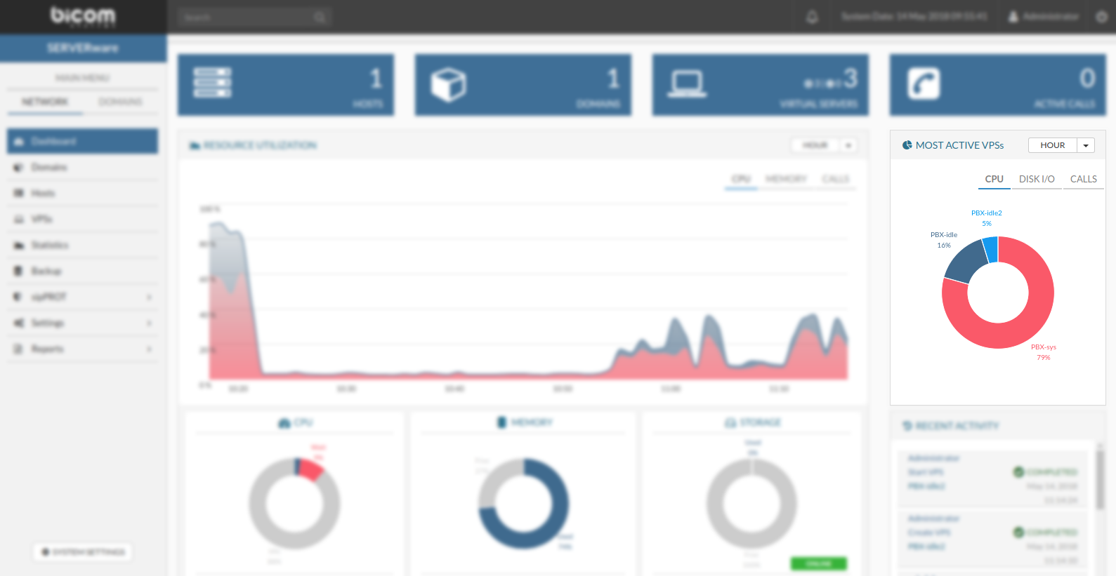
Most Active VPS's can be viewed in several time periods:
Also, there is a filter by resources used:
Calls statistics is dashboard widget displaying total number of calls made on all VPSs combined on SERVERware in different periods of time.
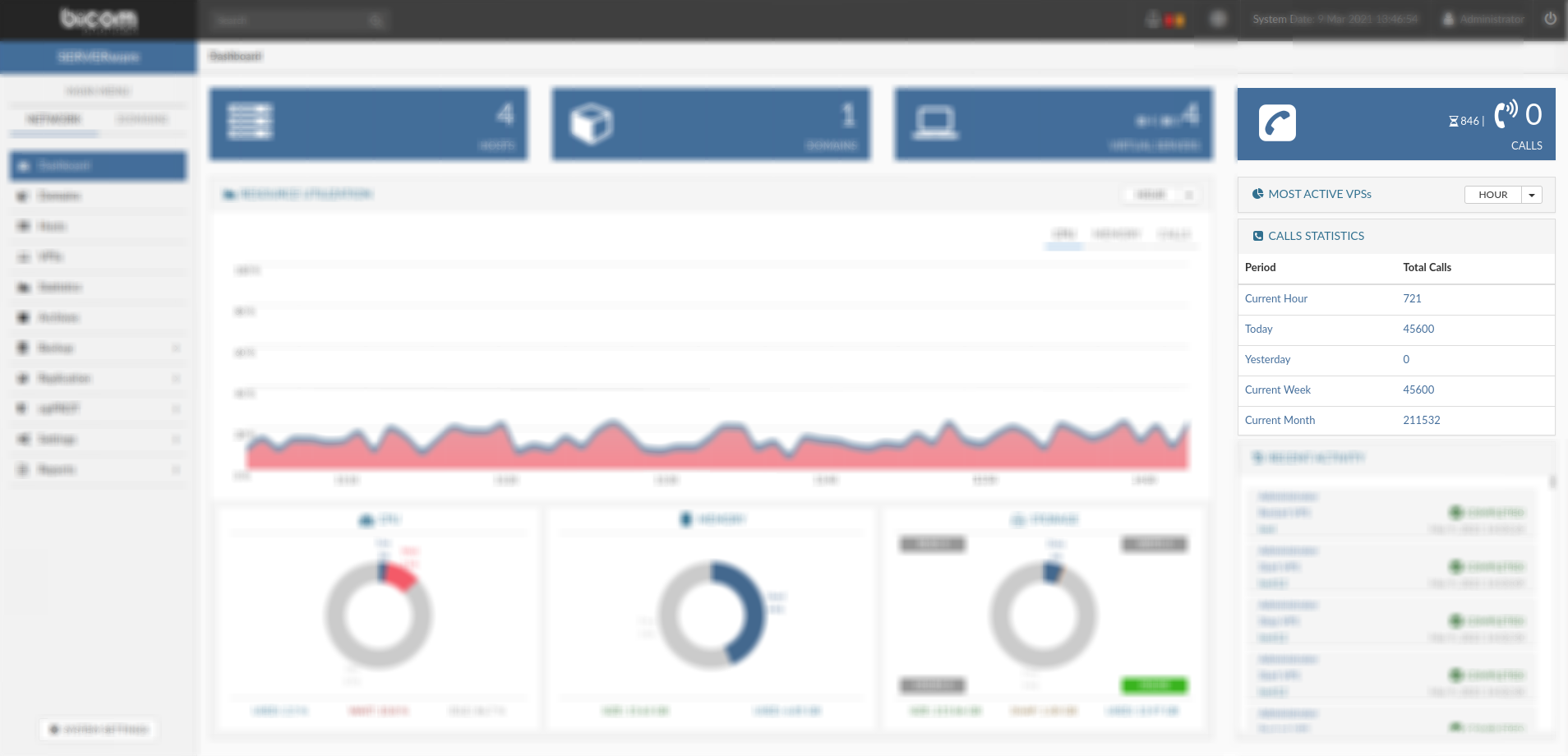
Calls statistics are displayed in several time periods:
Meeting statistics is dashboard widget displaying combined information for meetings made on all VPSs combined on SERVERware in different periods of time.
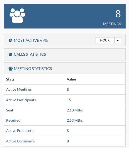
Meeting statistics are displayed in several time periods:
Memory and Storage dashboard displays over-commit on resources:

"LOCAL STORAGE" displays the local storage allocation for all processing hosts storage.

There are two bars for every storage pool "Used" and "Logical Used":
¶ BSSUP
¶ BSSUP panel
To access the BSSUP panel, click on the button next to the System Date in the top right SERVERware menu. BSSUP's main panel should appear on the right side of the SERVERware web interface. To close it, simply click again on the BSSUP button.
BSSUP panel has a clean and simple design with several buttons:
The status bar is at the bottom of the panel, which is showing whether SSH access is open or closed.
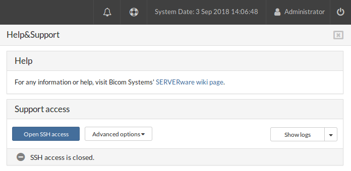
¶ SSH access
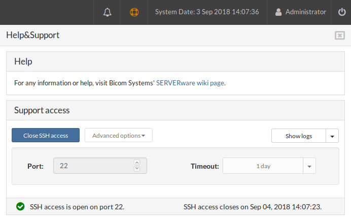
When SSH access is opened, an icon in the status bar changes color into green with the checkmark inside together with the SSH access status, indicating that everything is up and running on port 22. Also, the BSSUP panel button changes color into orange while the SSH access is opened.
Next, to the status information in the status bar, there is also info on when the SSH access will be closed.
During this stage, it's not possible to access Advanced options.
¶ Advanced Options
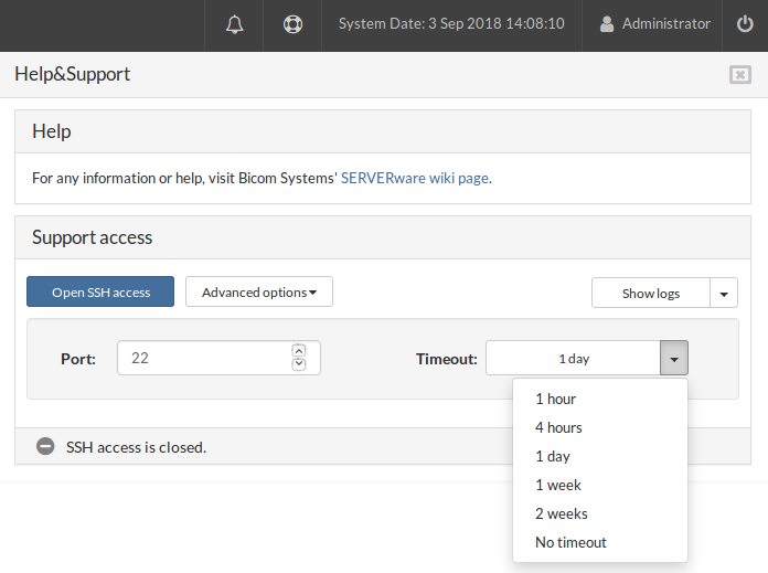
Port section is used to define which port will be used for SSH access. If you enter a text or invalid port value, the text field should be red, and the button for opening SSH access should be disabled.
The timeout dropdown menu is to choose for how long SSH access will be opened.
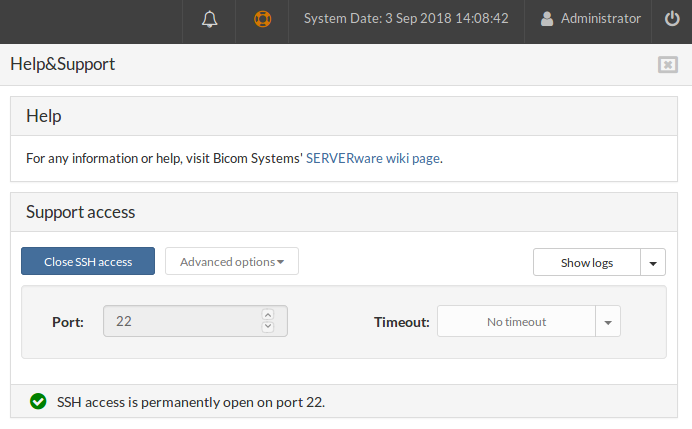
For example, if you enter 22 for the port, select No timeout and open SSH access, everything should be the same except the status bar. The message will show that the port is permanently open, and there should be no timeout.
¶ SSH access list
Open three separate terminals and in each one execute the command:
ssh root@IP_ADDRESS_OF_CONTROLLER -p22
After that, you should see something like this:
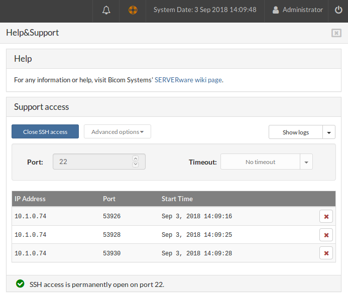
At the end of each connection status, there are buttons for stopping a single SSH session. When you click on one of the buttons, that row should disappear from the table, and on your terminal, you should get the output:
Connection to 10.1.50.10 closed by remote host.
Click on Close SSH access
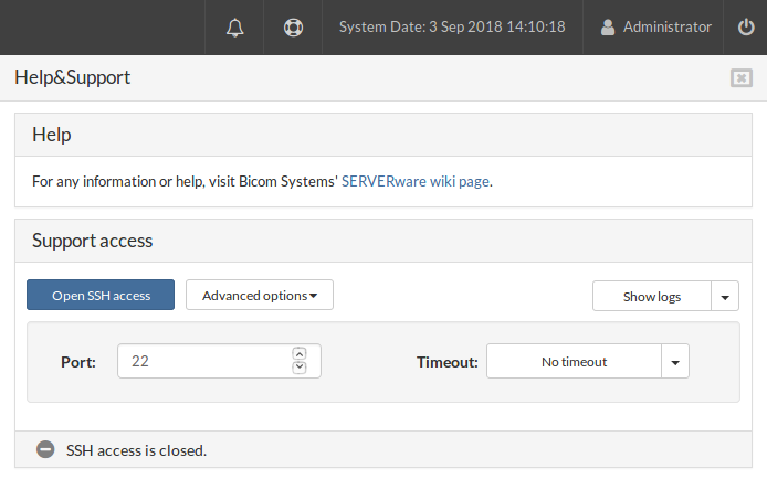
After clicking on Close SSH access:
¶ Logs
Click on Show logs
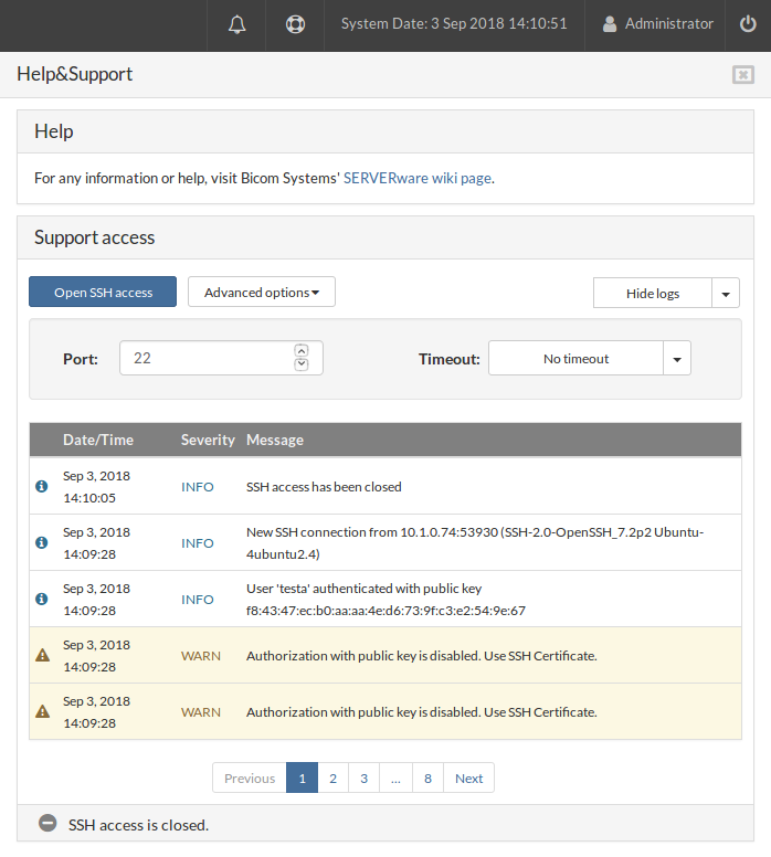
After clicking on the Show logs button, the BSSUP panel should expand with additional information regarding SSH access history, where you can find the date and time, severity, and detailed explanation of each SSH connection:
At the bottom of the log list, there is a page selector, together with the Previous and the Next buttons.
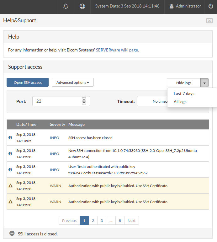
Above the log, there is a dropdown menu to choose for which period of time the logs should be displayed, All logs or for the Last 7 days.
¶ Partitions
A SERVERware Partition is a logical group of physical resources, users, and virtual servers. The main purpose of a partition is to define the administrative boundaries for the management of virtual private servers. A partition can represent an individual, department, or company.
¶ Managing Partitions
The Partitions menu item provides access to a graphical view of all the partitions in the system. The Partitions view consists of a partition list pane and a partition details pane. You can perform a management task on an individual partition by selecting the partition and then clicking the relevant action button.
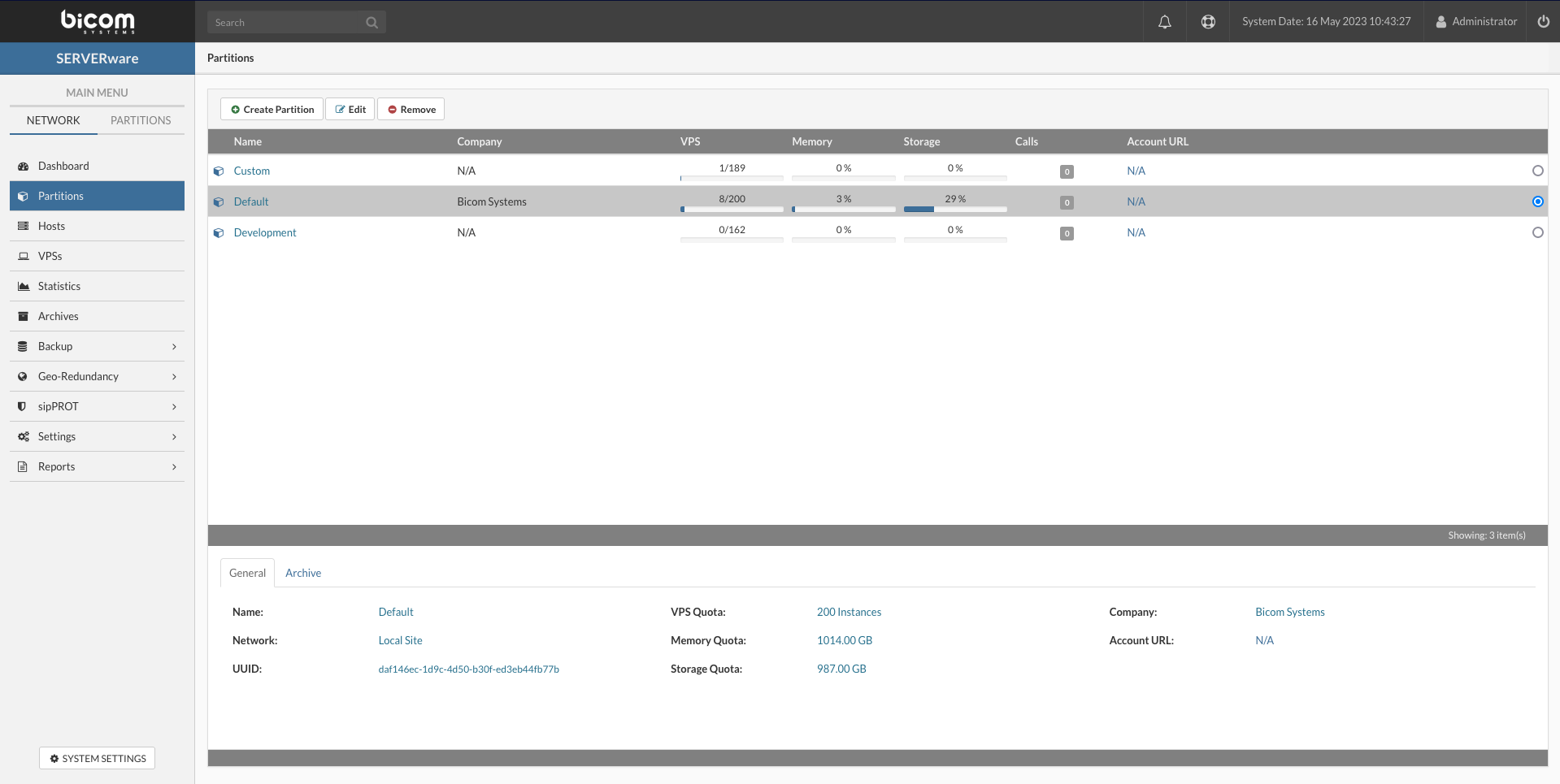
The following properties of the partition are displayed on the Partitions view as well as on the Create and Edit dialog boxes.
| Field | Description |
|---|---|
| Name | The partition name. Provide a descriptive name. |
| Company | Provide a company name to which partition belongs. |
| Account URL | An URL to a site or a CRM system containing more details about the company. |
| User Quota | A maximum number of partition members. |
| VPS Quota | A maximum number of VPSs that can be created within the partition. |
| Memory Quota | A maximum amount of RAM memory that can be utilized by the partition VPSs. |
| Storage Quota | A maximum amount of Storage space that can be utilized by the partition VPSs. |
The General tab on the Details pane provides information on an individual partition such as partition owner and resource quotas.
¶ Creating Partition
Follow this procedure to create a new partition:
On the "Partitions" view click "Create Partition" button.
The "Create Partition" dialog appears.
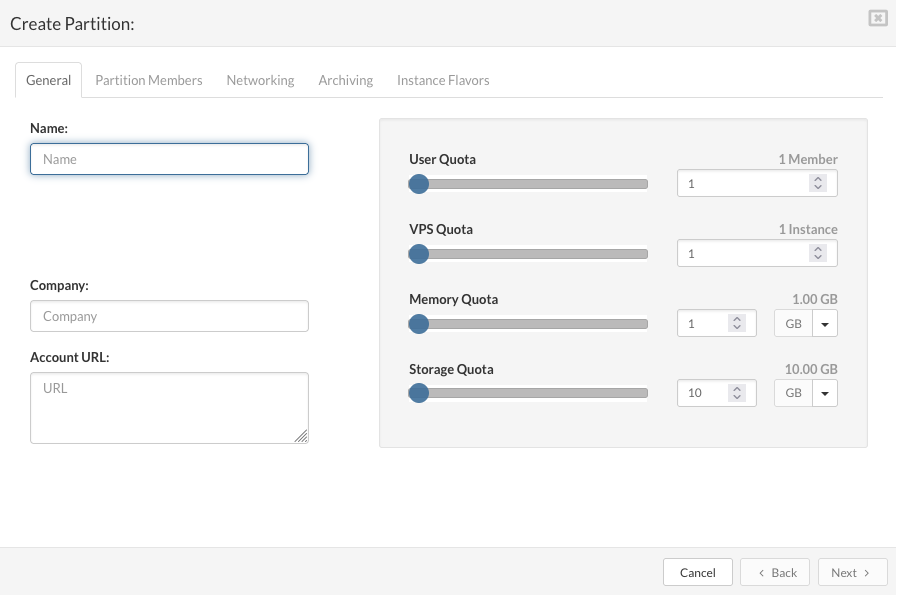
On the "General" tab enter the details in the following fields:
Name: a descriptive partition name.
Company: the company name to which the partition belongs.
Account URL: enter the company URL or leave empty.
User Quota: select max number of partition members.
VPS Quota: select max number of partition VPSs.
Memory Quota: select max amount of RAM memory for partition VPSs.
Storage Quota: select max amount of Storage space for partition VPSs.
Click the "Next" button to configure partition members on the "Partition Members" tab.
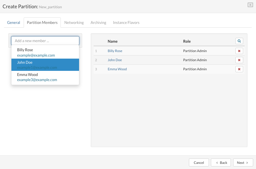
To "add a user" on the "Partition Members" tab, select or search an existing user in the dropdown list.
Selected user with a pre-assigned role appears in the list of partition members. Next time when logged in to the web interface, the new partition member will be able to login to the assigned partition and manage belonging VPSs.
To "remove a user", click the "Remove Member" button for the selected user. A confirmation dialog appears. Click "Remove". The user disappears from the partition member list.
Click the "Next" button to configure partition networking on the "Networking" tab.
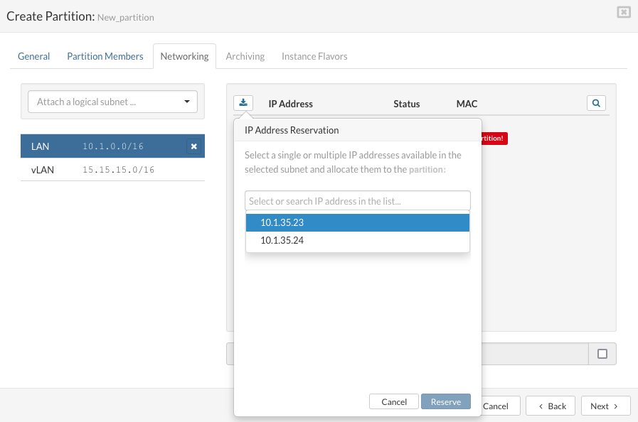
On the "Networking" tab select the logical subnet to which you want to connect partition VPSs.
Click on "Reserve Address" to open "IP Address Resevation" dialog. To "add a partition IP Address", select or search IP address in the list and click "Reserve".
Reserved IP Address shows up in the list. If there are no IP Addresses to select for reservation, use Settings/Networking menu to extend IP Address pool.
To "release a partition IP address", click the "Release Address" button for selected IP address. A confirmation dialog appears. Click "Release". The IP address disappears from the partition IP pool.
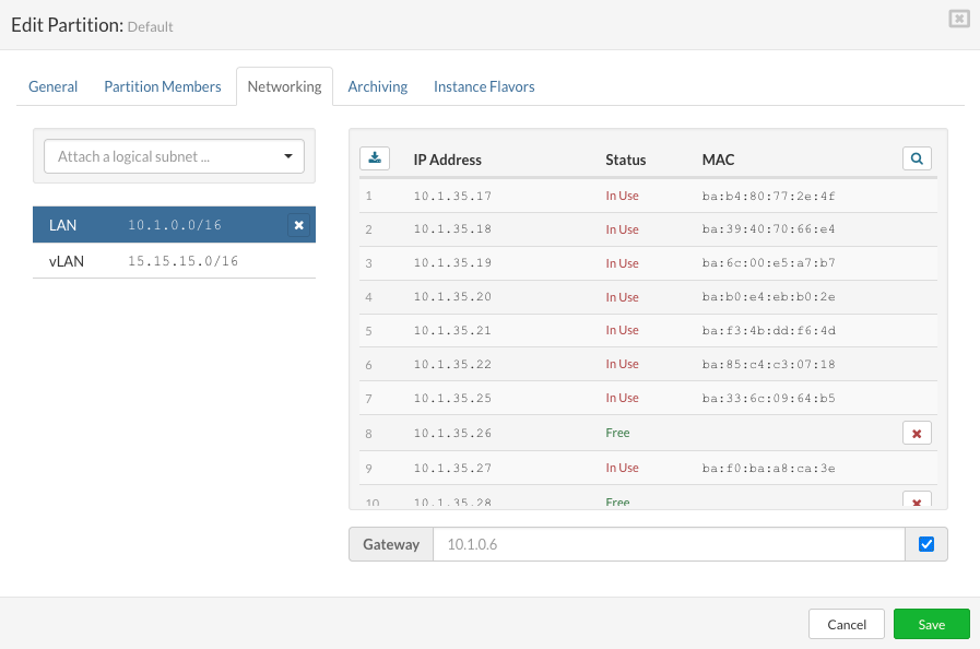
SERVERware administrators can specify a different gateway (instead of using the default one) when attaching a subnet to the partition so they can comply with specific ISP requirements of having a segmented network in a non-standard way.
Click the "Next" button to configure "Flavors" tab and select resource flavors for partition VPSs.
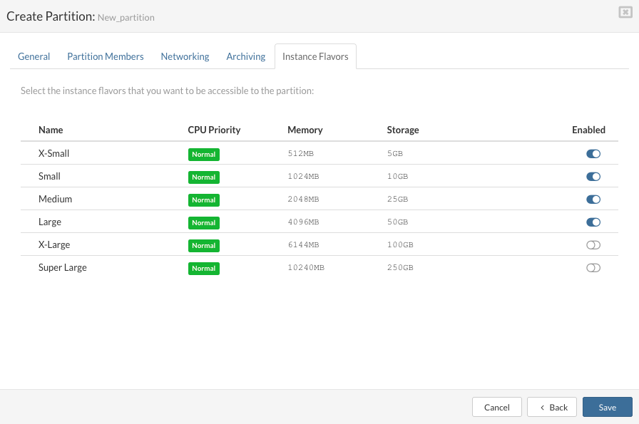
Turn on the resource flavors that you want to be accessible to the partition.
Click the "Finish" button to initialize the partition creation.
A new entry presenting the new partition appears in the list.
¶ Editing Partition
You can edit the details of a partition, such as its name, resource quotas, partition members, networking, and flavors.
Follow this procedure to edit partition details:
¶ Removing Partition
A SERVERware partition can be removed only if there are no VPSs that belong to it.
Follow this procedure to remove a partition:
¶ Hosts
A SERVERware host is a physical 64-bit server running a special build of Gentoo Linux, configured with packages required to host virtual servers. Based on a purpose, SERVERware defines the following three types of hosts:
¶ Managing Host
The Hosts menu item provides access to a graphical view of all the hosts in the system. The Hosts view consists of a host list pane and a host details pane. You can perform a management task on an individual host by selecting the host and then clicking the relevant action button. If an action is not possible, the button is disabled.
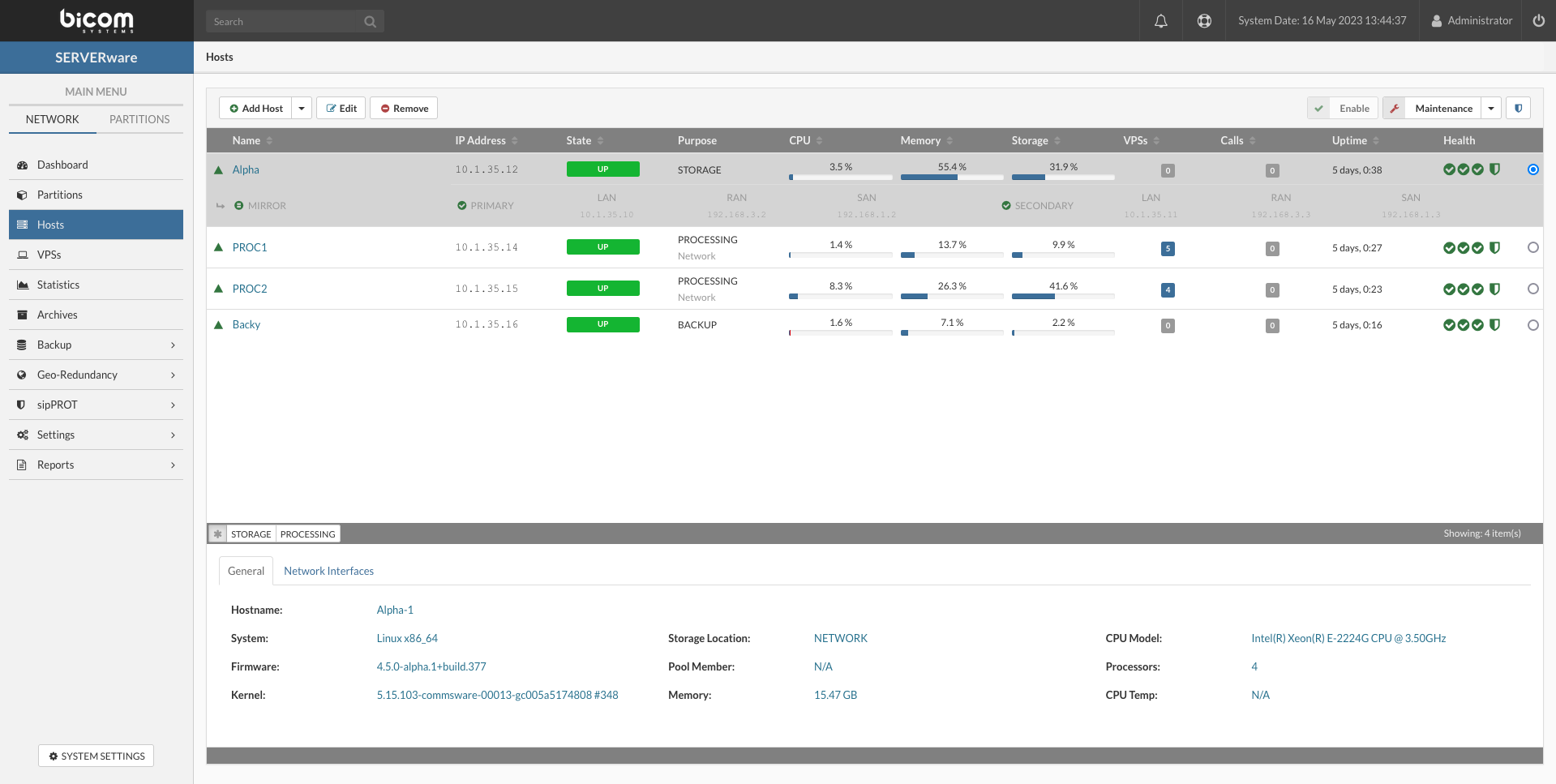
The General tab on the Details pane provides information on an individual host, including hardware and software versions. The Network Interfaces tab on the Details pane provides information about the logical and physical networks of the host. This allows you to define the attachment of the logical subnets to the physical network interface cards of the host.
¶ Adding Host
Hosts must be correctly installed before you can add them to the SERVERware virtualization platform. Before adding hosts ensure that the IP Address has been assigned correctly. There is no need to additionally configure Network Bridge which is automatically created during the installation. Network Bridge allows Virtual Servers to interact with the network as if they were using physical NICs.
To add a SERVERware host, follow the next steps:
On the Hosts view, click Add Host button.
The Add Host dialog appears.
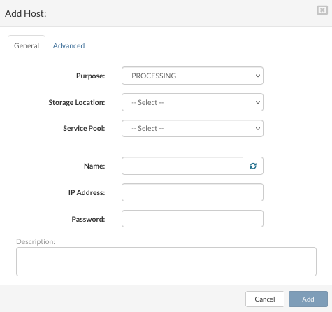
Enter the details in the following fields:
Purpose: the purpose of the host.
Storage Location: the storage location field appears only when the selected host purpose is the processing. Select the Network Storage as a storage location for VPS volumes.
Service Pool: the service pool such as the storage location makes sense only for the processing hosts. Select the Mixed pool.
Name: a descriptive name for the host. Use a button for generating a random hostname if the name is not so important.
IP Address: the IP address of the host which was provided during installation.
Root Password: the password of the designated host. If not manually changed on the host, the default password is serverware so you will be asked to provide a new password as soon as you enter the default one into the field.
On the Advanced tab you can edit SW-Connector Port (default is 4433) and you can enable/disable Forward logs to the central syslog server by checking/unchecking box.
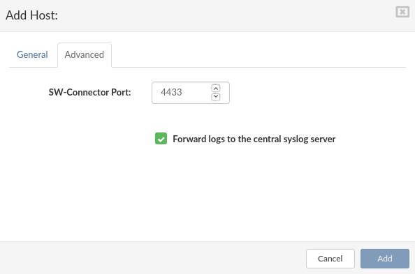
Click Add button to submit the form.
The new host appears in the list of hosts with a ''disabled'' state. The host health indicators for the connection and SW-connector should be green circles. Depending on it whether the host SAN network interface was pre-configured or not, the Storage connectivity indicator will be a green or red circle.
¶ Enabling Host
After a host has been added, updated or an existing host has been taken down for maintenance, it needs to be enabled before it can be used.
The host state changes to UP. Virtual servers can now run on the host.
¶ Managing Host Network Interfaces
The Network Interfaces tab on the Details pane of a host allows you to define the attachment of the logical subnet to the physical network interface cards (or NICs) of the host. This is a simple operation in which you attach one or more of the host's physical network interface cards (NICs) to a predefined logical subnet in the SERVERware environment.
There are three logical subnets defined by SERVERware during installation:
The Network Interfaces tab displays the name, logical subnet name, IP address, subnet mask, MAC address, and link status for each host interface. There is an Edit button next to each interface. The network interface configured during the host installation is automatically assigned to the LAN subnet. Given that the LAN interface is used for the host management, it is not safe to edit the LAN interface from the administration GUI. RAN interface is used by storage servers only and is configured automatically by the setup wizard. The SAN interface is only used in the SERVERware Cluster Edition. It is automatically set up on the storage servers by the setup wizard but needs to be configured upon the new processing host addition.
In the Hosts view, select the appropriate host.
Click Maintenance button to switch host into maintenance mode.
Click Network Interface tab on the Details pane to display the list of NICs on the host, their address and other specifications.
Click the Edit button next to NIC that you want to edit. Edit Host Network Interface dialog appears.
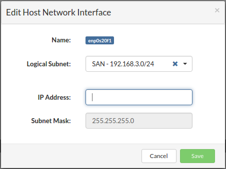
Select a logical subnet from the list to attach NIC to a different logical subnet.
Provide an IP address belonging to the selected logical subnet.
Click Save button to apply the changes.
Click Enable button to enable host.
¶ Maintaining Hosts
¶ Moving host into Maintenance Mode
Hosts must occasionally be brought down for maintenance. You have to manually migrate or stop all virtual servers, before shutting them down. Placing a Host into maintenance mode is a way to notify SERVERware Controller that the host is no longer a stable resource for VPS hosting and cannot be used as a target host for new VPSs as well as a target for VPSs migration or failover.
WARNING: If any virtual servers stay running on the host placed into maintenance mode, be aware that they will not be automatically failed over in the case of a host failure.
Follow the below-mentioned steps to move a host into maintenance mode:
The host status stays unchanged if SERVERware Controller is unable to communicate with and control the host.
¶ Editing Host Details
You can edit the details of a host, such as its name or network configuration.
Follow this procedure to edit host details:
¶ Removing Host
Hosts that are no longer being used by SERVERware can be permanently removed. A host removing the action is allowed only for the processing hosts. A processing host can be removed only if there is no hosted VPSs on it. So, to remove a processing host for any reason make sure that you have previously moved all VPSs to another processing host.
Follow this procedure to remove a host:
¶ Evacuate VPSs
If it's necessary to quickly evacuate all VPSs running on a processing host due to the maintenance tasks so you do not have to repeat multiple steps for each VPS, VPSes can be transferred from one host to another using Evacuate VPSes option in the Hosts menu. The evacuation process is implemented in a way that all VPS will be returned to their initial state as was at the point the evacuation is triggered.
For Evacuate VPSes feature to work the Host which is evacuating must be in Maintenance mode.

Follow this procedure to evacuate VPSes from the host:
In the Host view, select the host to be evacuated.
Click the Maintenance button. A confirmation dialog appears.
Click Yes. Selected Host switch into maintenance mode.
In upper right corner click on Evacuate VPSes
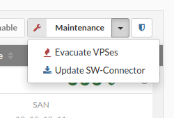
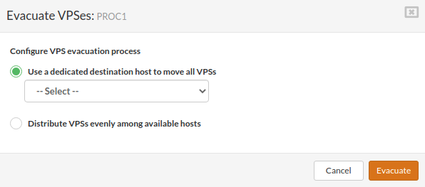
Clicking the “Evacuate VPSs“ button will open a small dialog box that will ask the administrator to select a host to which VPSs will be moved or to let the system to distribute VPSs evenly across all processing hosts in the cluster.
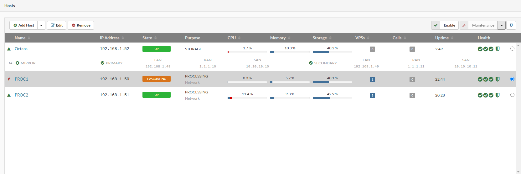
Once the evacuation is initiated, the host state label (MAINTENANCE) will be hidden and in that place, the word “EVACUATING“ will appear and stay so long until the evacuation is completed.
¶ Undo Evacuate VPSs
The evacuate action must be run before the undo evacuation. Undo evacuate will ensure that the host goes back to the state before the "Evacuate VPS" action, this is possible only if the evacuated VPSs are not moved further after the Evacuate action.
¶ Updating Host SW-Connector
The sw-connector service agent running on hosts is a crucial component for the proper functioning of the SERVERware environment, so it has to be updated if there are new features or bug fixes. A host should be moved to maintenance mode before updating the sw-connector.

Follow this steps to update sw-connector:
¶ Virtual Private Servers (VPSs)
The VPSs menu provides a graphical view of virtual servers that the connected user is permitted to administer. The VPS list pane allows you to perform a management task on an individual VPSs while the VPS details pane provides information such as details about allocated resources, owner name, network interfaces, and storage.
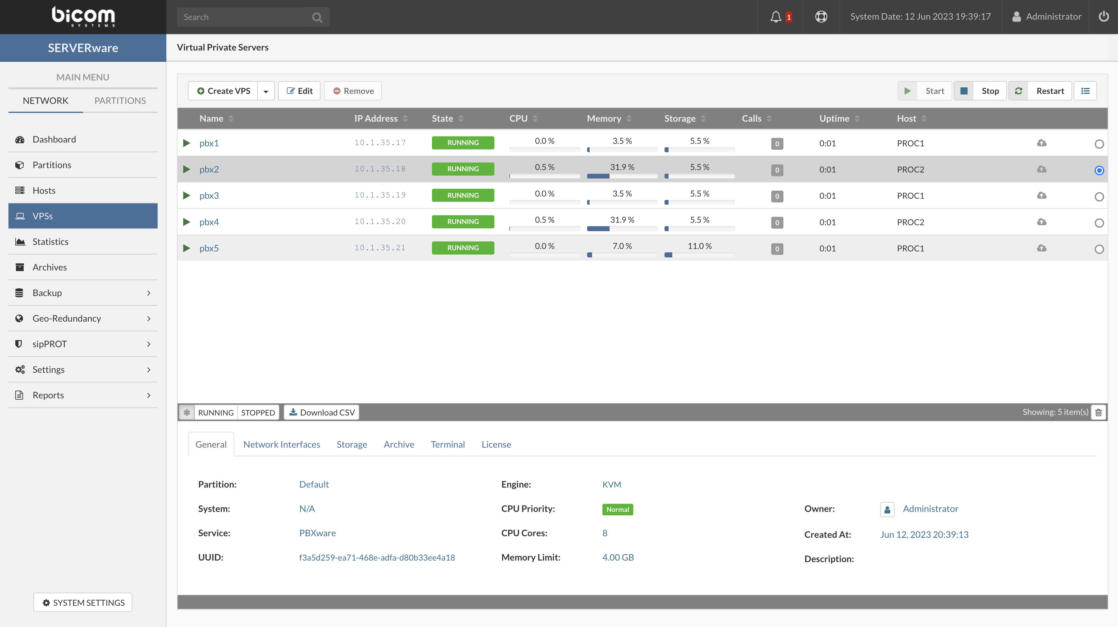
The General tab on the Details pane provides information on an individual VPS such as base template version, the partition it belongs to, owner name as well as details about allocated resources.
The Network Interfaces tab provides information about logical subnets to which VPS is attached.
The Storage tab provides information about VPS storage volume, location, and size. It
allows you to increase the size of the storage assigned to the VPS.
The Archive tab show info (archive URL, health and storage) about Archive service if enabled on VPS
The Terminal allows to open TTY session for selectet VPS in the same tab.
¶ Creating New Virtual Private Server
In order to provide a simple and fast way of creating a new virtual server instance, SERVERware provides virtual server templates. A template is a base virtual server that is set with a unique configuration and settings. A virtual server that is based on a particular template acquires the configurations and settings from the template. Thus, templates are used to conveniently and efficiently create a set of identical virtual servers. By default, virtual servers created from templates use thin provisioning. In the context of templates, thin provisioning means that all virtual machines based on a given template share the same base image as the template.
There are three types of templates in SERVERware:
Beside that all VPSs are supported with two engines:
KVM stands for Kernel-based Virtual Machine and is based on Firecracker, an open source virtualization technology that is purposely built for creating and managing secure, multi-tenant container services.
With KVM, each VPS has a fully emulated or virtualized machine to run its copy of the Linux kernel, providing better isolation at the cost of some additional performance. From a security standpoint, this is a much better approach to partitioning resources between multiple services and their users. SERVERware’s implementation of KVM can run unmodified Linux containers as VPSs which can either be PBXware or Docker containers fetched as OCI images from Docker Hub and similar sources. Additionally, one can pack and distribute service software using open standards and tools.
Follow this procedure to create a new virtual server:
On the Virtual Private Servers view click Create VPS button.
The Create VPS dialog appears.
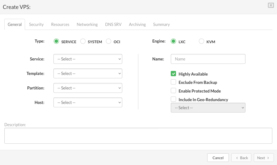
On the General tab enter the details in the following fields:
Type: the type of virtual server to be created.
Service: a service that VPS has to provide. This field appears if a selected VPS type is the service. Select a service name from the list.
Template: the base virtual server version for selected VPS type. Select a template from the list.
Partition: the partition which VPS belongs to.
Host: the host on which VPS will be created
Engine: type of engine on which VPS will be running
Name: a descriptive name of VPS.
Highly Available: enable failover of VPS to storage host.
Exclude From Backup: if selected the VPS will be excluded from backup.
Enable Protected Mode: if selected only administrator can manage VPS ( start, stop, restart).
Include in replication: if selected the dropdown with the list of available enabled replications will appear (select the replication from dropdown to add the created vps to the replication cycle).
Description: Describe VPS if necessary.
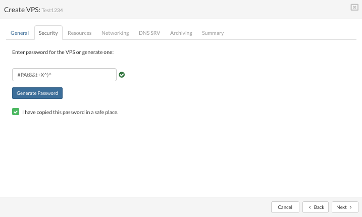
Click the Next button to configure Security tab.
Password field: enter password manually (existing password will not be displayed here).
Generate password: serverware will generate the new password.
Check box: select to confirm the password is copied to a safe place
Click the Next button to configure VPS resources on the Resources tab.
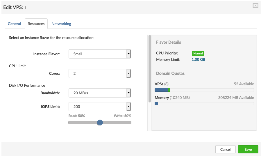
On the Resources tab enter the details in the following fields:
Flavor: a resource flavor. Select a flavor from the list that provides a resource ratio which fits the VPS needs.
CPU: limit CPU cores for per VPS. values available :
The default values for CPU limits are inherited from the selected resource flavor.
Bandwith: limit disk read/write bandwith in MB/s
IOPS Limit: Limiting IOPS per VPS. The default value to be 150 With several other options included:
The default values for Read/Write IOPS limits are inherited from the selected resource flavor.
AstDB RAM Disk: a size of RAM disk to keep Asterisk database. This affects PBXware based VPSs only and should be configured only if you detect a performance issue.
Call Recordings RAM Disk: a size of RAM disk to keep call recordings. (PBXware only)
Mount points :
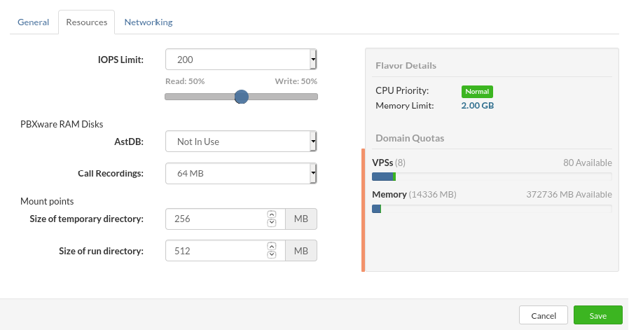
Assign the size of the mounted folder on /tmp for VPS.
• Size of temporary directory:
Temp directory size larger than 50% of RAM given to VPS is not recommended.
Assign the size of the mounted folder on /run for VPS.
• Size of run directory:
Run directory size larger than 25% of RAM given to VPS is not recommended.
Click the Next button to configure VPS networking on the Networking tab.
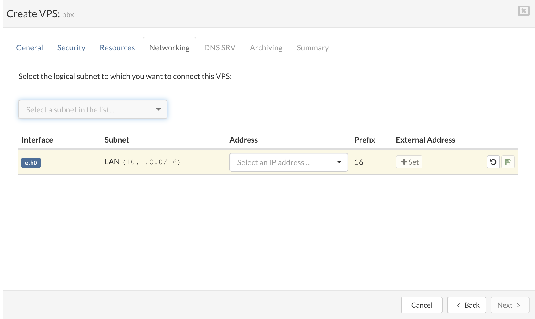
On the Networking tab select the logical subnet to which you want to connect the VPS.
Enter an IP Address belonging to the selected logical subnet.
Click the Next button to show the Archiving tab (will show only if archive service is enabled on partition).
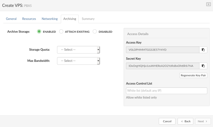
Review the summary information and click Finish button to initialize VPS creation.
A new entry presenting the new VPS showing a current task status appears in the list.
Click the Next button to configure DNS SRV + NAPTR record if configured.
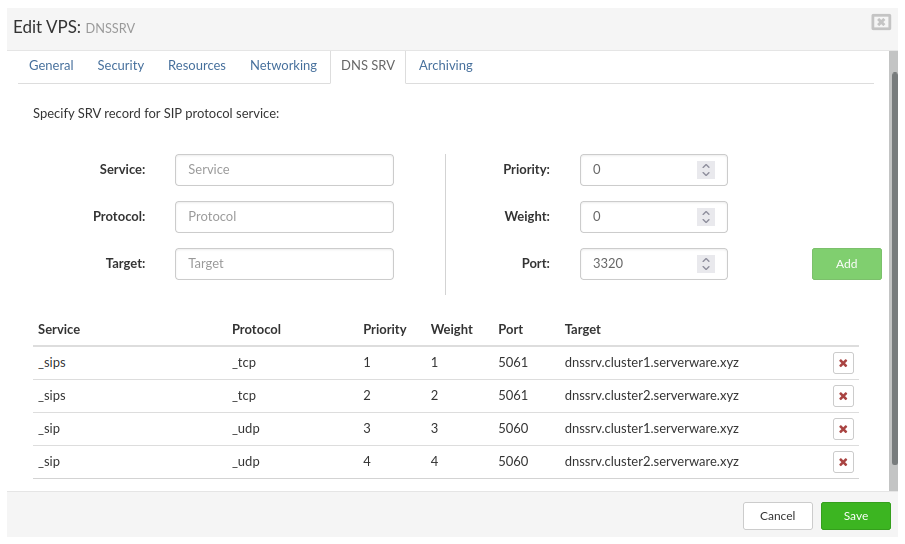
The DNS lookup routine looks for SRV records first. Proper use of SRV records permits the administrator to distribute a service across multiple hosts within a partition, to move the service from host to host without disruption, and to designate certain hosts as primary and others as alternates.
To set up DNS SRV record on the PBXware VPS
Populate the fields with the data required and press Save.
service
Symbolic name of the service.
The service name is what the client accepts as service (for IP telephony service used is "_sip" or for TLS "_sips").
Protocol
Protocol used to access the service. The SIP clients accept either "_tcp" or "_udp" depending on the client configuration. TLS will only work with "_tcp".
Target
Partition name associated with the resource record.
In the partition name, we will enter the full path to our PBXware VPS including the VPS name "vpsname.cluster1.serverware.xyz")
priority
Service priority. Servers are ordered by priority with the lower priority numbers ordered before the higher priority numbers. Set the priority to 0 if the priority order is not wanted.
weight
Load balancing within the same priority. A higher weight number indicates that the server can handle more requests than a lower weight number. The probability that a server is ordered early in the list increases as the weight increases. Set the weight to 0 if load balancing is not wanted. Otherwise, use nonzero values for all the weights within the same priority. (An SRV record with a weight of 0 has a low probability of being ordered before an SRV record with a nonzero weight).
port
The port number is assigned to the SIP service. This value would be "5060" or "5061" for TLS.
While it is preferable to use a single SRV record for each sip server, some implementations might require multiple SRV records with a single service record for each resource name. As there are some clients on "TCP" and some on the "UDP" on the same service.
Now we can save the configuration and start VPS.
¶ Create VPS from OCI image
When creating the VPS from the OCI image first we have to download the OCI image from the repository and add it to SERVERware templates, see "OCI image Template" section.
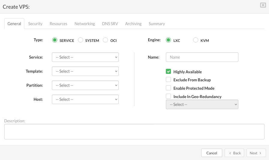
You will notice that we have a new Environment tab appear when OCI is selected as a source
Example for MySQL :
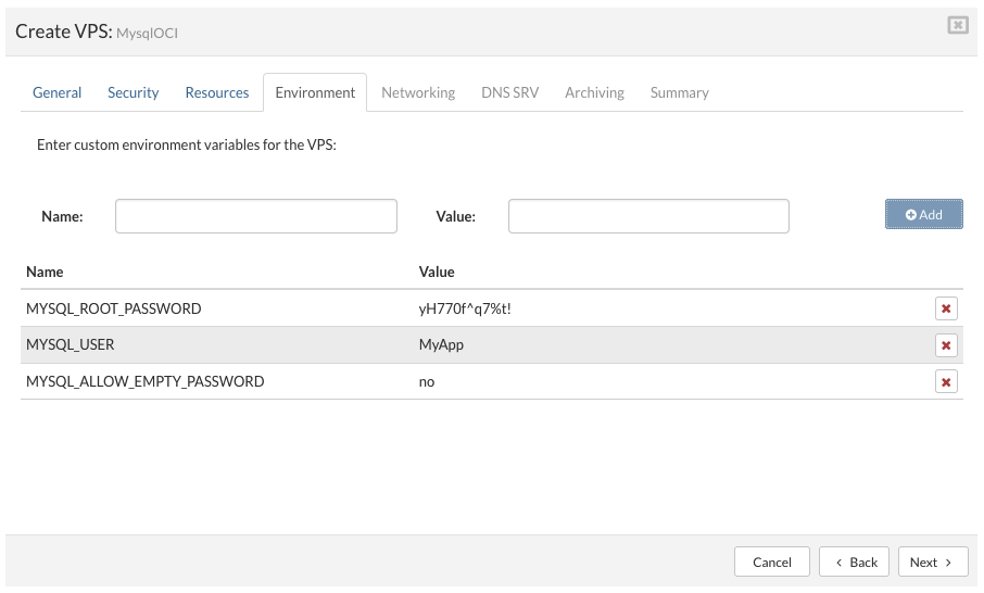
Here we can add some external environment variables needed for the OCI image to function properly, the available environment variables are listed in the docker hub for the image used.
Finish the steps to the end and hit create button, after this, we will have a functional VPS created from the OCI image.
¶ Managing Virtual Private Servers
Administrative tasks for virtual servers include:
¶ Editing VPSs
You can edit details of a virtual server such as its name or memory size. However, you cannot change the template or the partition to which the virtual server belong. Also VPS engine change is possible only when VPS is stopped The VPS network configuration changes take effects after the virtual server is stopped and restarted.
Follow this procedure to edit VPS details:
¶ Starting, Stopping and Restarting VPSs
Management actions such as VPS starting, stopping, and restart is performed directly on the virtual server by using dedicated buttons for that purpose located on the top of the virtual server list.

Follow this procedure to trigger a VPS management action:
¶ Changing VPS Ownership

Follow this procedure to change VPS owner:
¶ Increasing VPS storage
Follow this procedure to increase VPS storage space:
In the Virtual Private Servers view, select the VPS for which you need to increase storage space.
If the VPS that you want to change is not visible in the list, perform a search.
Select Storage tab and click the Extend Volume button.
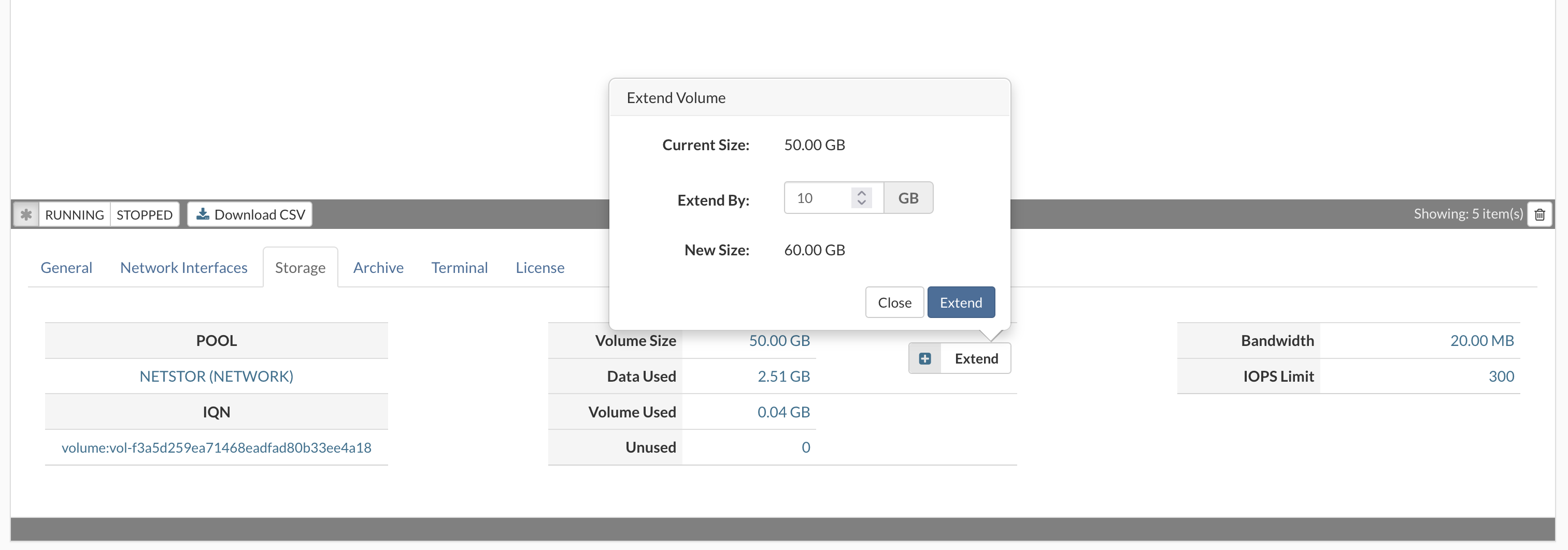
Extend Volume dialog appears.
Select an amount you wish to increase storage space for and click the Extend button to increase storage.
¶ Reclaim free space - TRIM
Follow this procedure to reclaim VPS storage free space (VPS must be stopped):
In the Virtual Private Servers view, select the VPS for which you need to reclaim free space.
If the VPS that you want to change is not visible in the list, perform a search and stop VPS.
Select Storage tab and click the Trim button.
Trim storage dialog appears, click YES to start trim process.
The trim feature will be available only when there is more than 10% of unused space for trim

¶ Open TTY session on VPS
TTY is passwordless CLI VPS access from SERVERware GUI. In case of misconfigured ssh, custom templates without an ssh client or for any other reason ssh might be inaccessible.
TTY session will provide easy access for troubleshooting. This is the internal SERVERware service, so it does not depend on the status of services in the VPS.
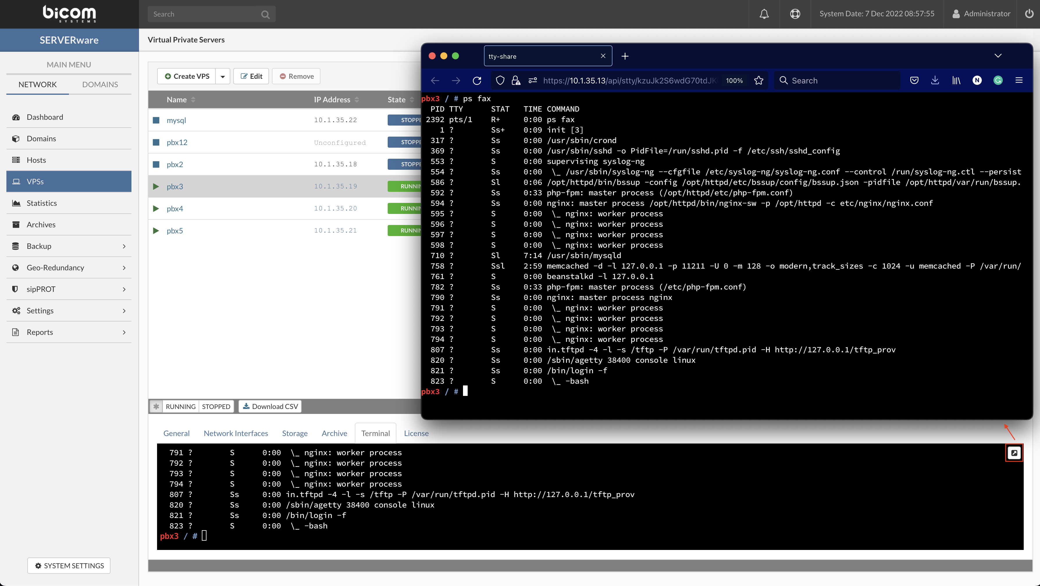
You can open multiple TTY sessions on a single VPS and TTY session for any VPS from SERVERware GUI.
We strongly advise you to use some kind of screening tool for performing actions that can take longer than 30 min (tmux, screen, etc..)
Steps:
¶ Moving VPSs
A stopped VPS can be moved to any processing host within the SERVERware network. This is especially useful if the load on a particular host is too high, and is essential before bringing a server down for maintenance. A live VPS migration is not yet supported. Also, while VPS is stopped, it is possible to move a VPS to another partition.
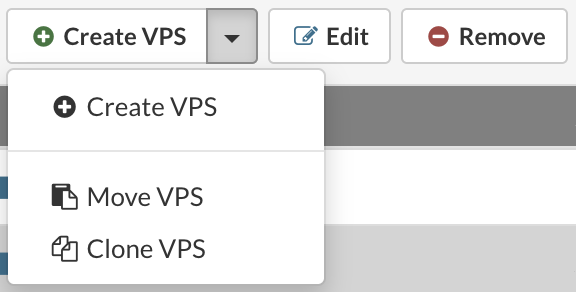
Follow this procedure to move VPS to another host:
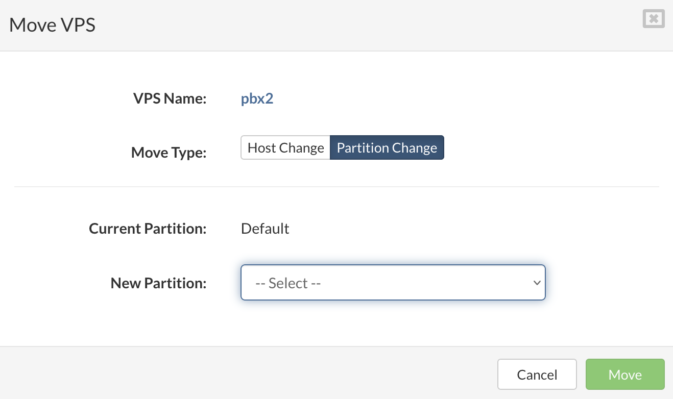
Follow this procedure to move VPS to another partition:
¶ Cloning VPSs
In SERVERware, a VPS can be cloned regardless if VPS is stopped or still running. This is especially useful for creating multiple instances of already configured and running VPSs.
Follow this procedure to clone VPS:
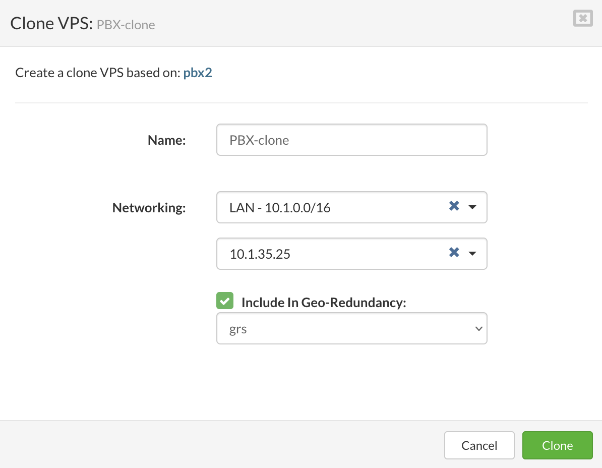
¶ Removing VPSs
VPS can be removed only if it is stopped.
Follow this procedure to remove a VPS:
¶ Removing VPSs from the Removed VPSs list
When removed, VPSs move to the Removed VPSs list, which acts like a recycle bin as it is possible to restore listed VPSs.
If the removed VPS has a backup, it would be possible to restore that VPS from the removed VPSs menu.
To restore the removed VPS, follow these steps:
Removed VPS will be automatically removed from SERVERware inventory once their latest backup expires
¶ Statistics
The SERVERware statistics module collects data about the resource usage by Hosts as well as VPSs. Data on a wide range of metrics is collected at frequent intervals, processed and archived in the SERVERware database.
¶ View Host/VPS Performance Charts
The Statistics menu item provides access to a statistic chart view. The Statistics view consists of a chart settings pane and a chart view pane. On the statistic view, you can see both Host and VPS performance charts as well as do a performance comparison between Hosts/VPSs. The following metrics are available in the chart settings:
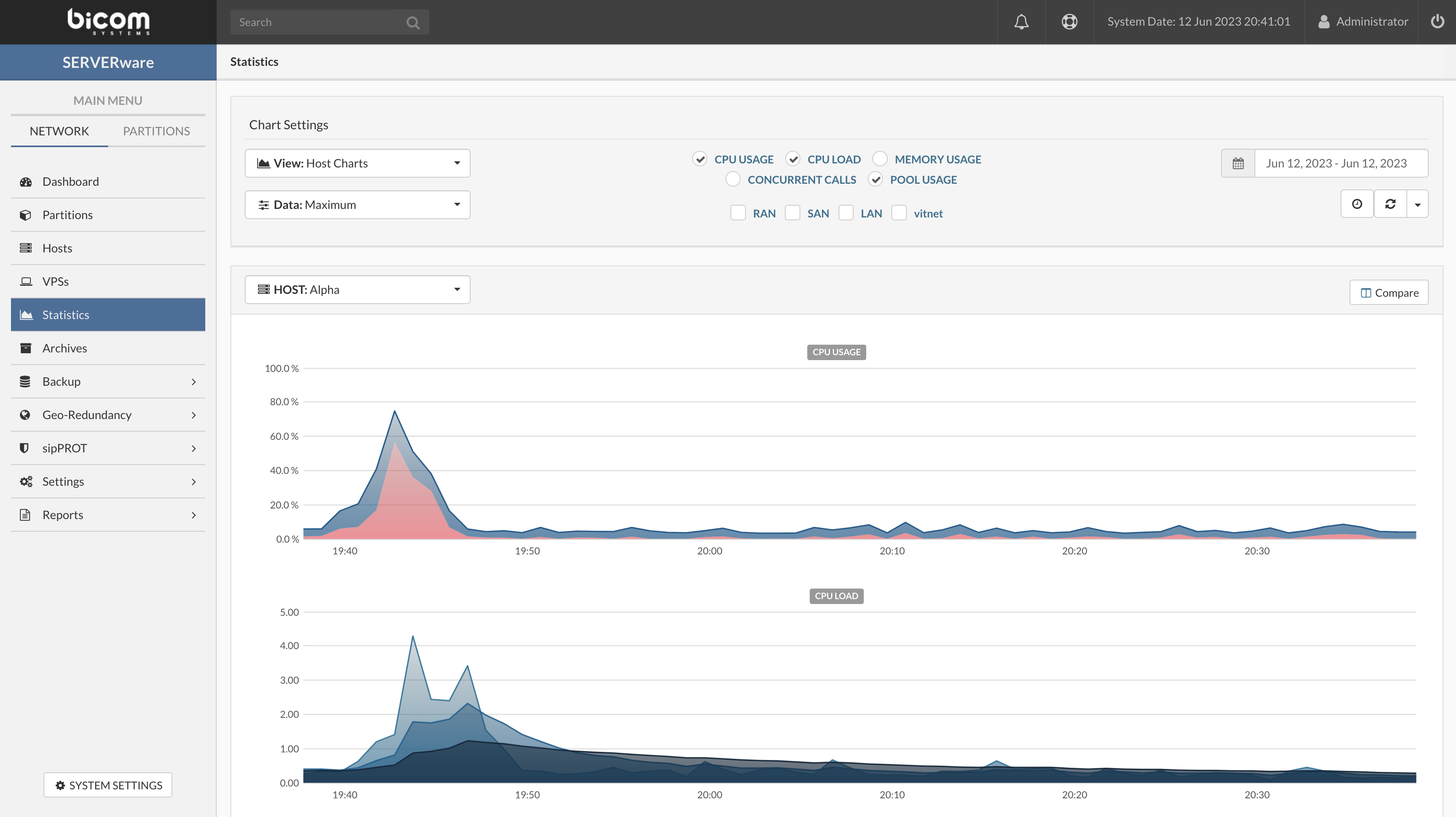
Follow this procedure to view Host/VPS performance charts:
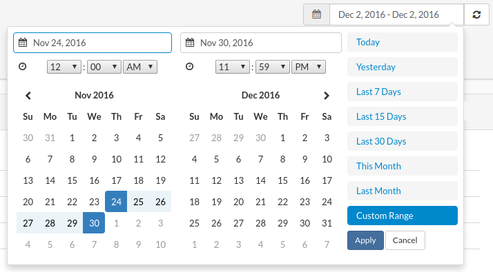
Select a Host/VPS which performance charts you want to show.
Click the Compare button if you want to compare the performance of different Hosts/VPSs.
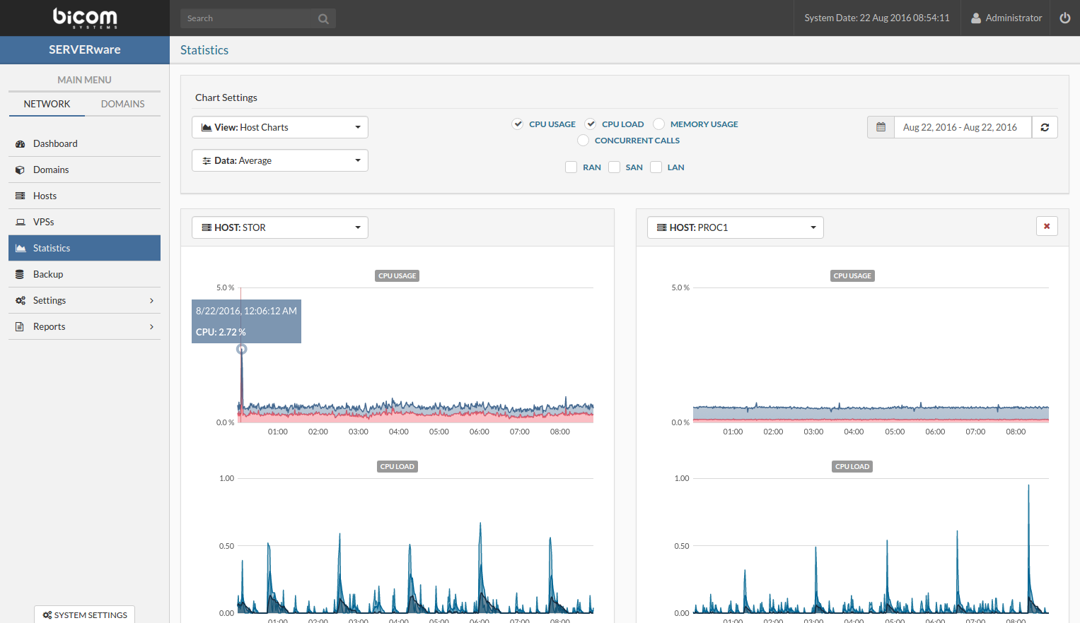
¶ Backup
In order to provide fault-tolerant storage, SERVERware relies on a mirrored pair of storage servers. Given that the storage mirror by definition and purpose is not a backup, SERVERware provides a built-in backup feature to protect data of hosted VPSs in the event of a disaster.
¶ Manage Backup Jobs
The Backup menu item provides access to a backup Schedule and Browse & Restore submenu. The Schedule view consists of a list of scheduled backup jobs below which is a pane showing the backup job history for a selected backup job. The Browse & Restore view consists of a list of backup hosts on which backups are placed and then select a backup host and backup set below there is a pane showing the VPS restore points.
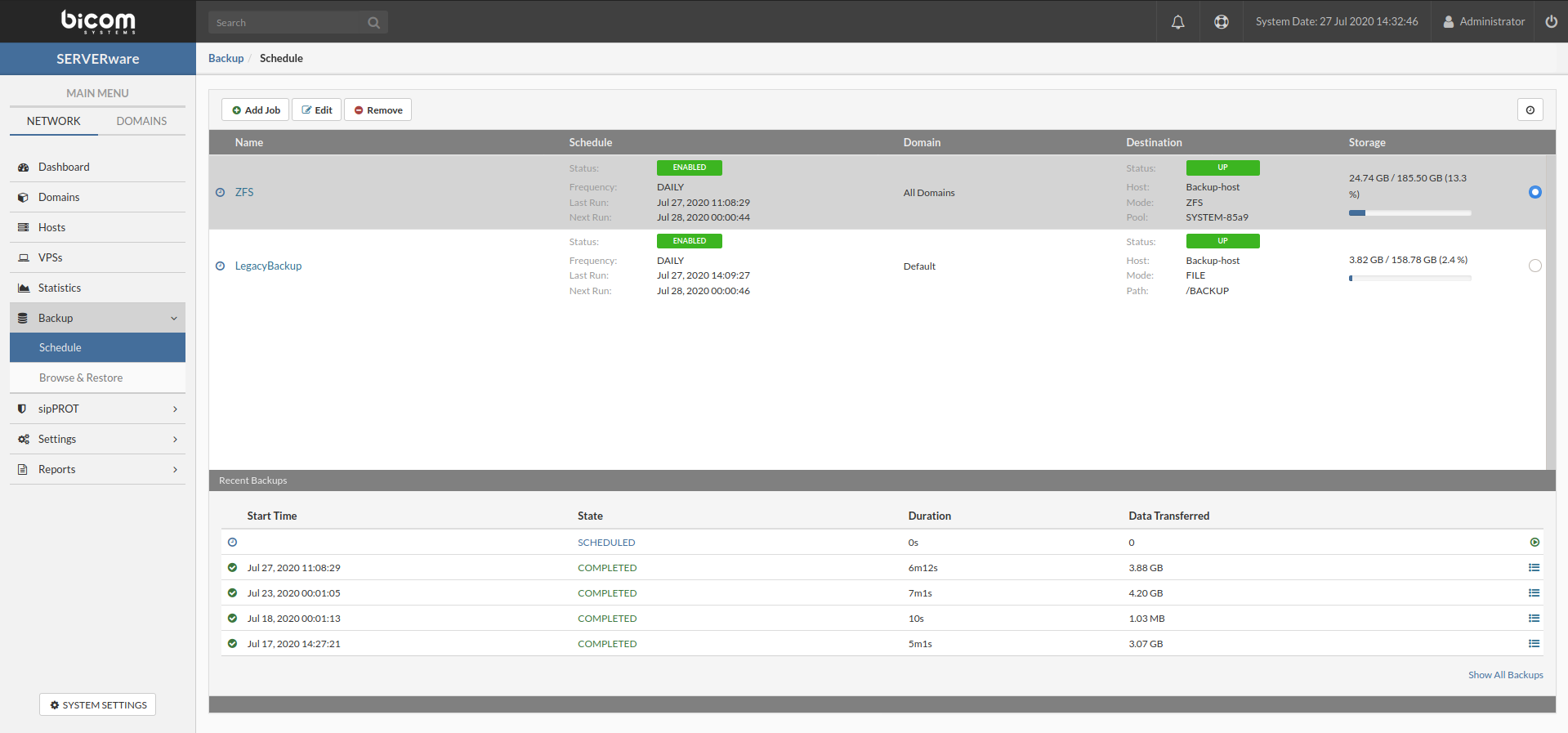
The following properties of a backup job are displayed on the Backup view as well as on the Add and Edit dialog boxes.
| Field | Description | |
|---|---|---|
| Name | The backup job name. Provide a descriptive name. | |
| Mode | Available choices for the backup Mode are Backup to ZFS and Backup to File (legacy) | |
| Partition | The name of partition from which you want to backup VPSs. It may be an individual partition or all partitions in the network. | |
| Destination | The name of a host dedicated to backup. It may be the existing Network Storage host, however, this is not recommended. | |
| Pool | The name of the backup dedicated pool. | |
¶ Schedule Backup Job
It is possible to create any new dataset for backup purposes just by setting srw:dstype property to 'backup'. By default SERVERware set 'backup' property on SYSTEM-xxxx/BACKUP dataset.
But if user want to create a new dataset for backup it is necessary to create a folder for new dataset eg. /newbackup. Then create zfs dataset, mount /newbackup folder to that dataset and set 'backup' property using following command:
~ # mkdir /newbackup
~ # zfs create SYSTEM-XXXX/newbackup -o mountpoint=/newbackup -o overlay=on -o compression=on -o srw:dstype=backup
A newly created dataset for the backup will be available for selection when scheduling a backup job.
Follow this procedure to schedule a backup job:
On the Backup view click Schedule then click on Add Job button.
The Create Backup Job dialog appears.
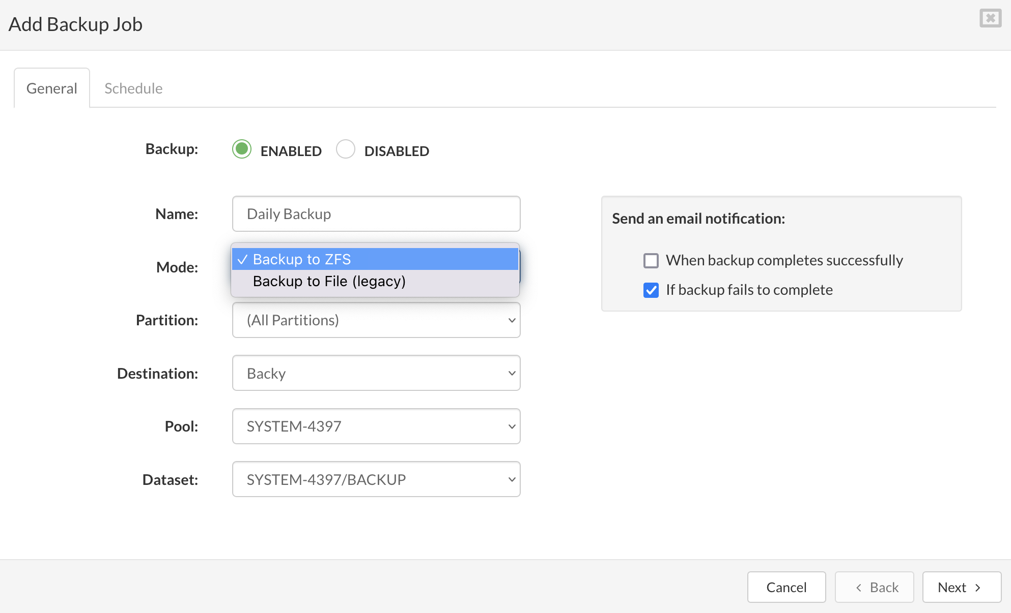
Enter the details in the following fields:
Job Name: Descriptive backup job name (e.g. Daily Backup).
VPSs From: Select a source partition if you want to create a backup job for VPSs running on that partition only or leave default (''All Partitions'') to backup all VPSs running on all partitions.
Destination: Select a host for backup destination. It is recommended to have a dedicated host for storing backups.
Path/Pool: File system path on which to store backups.
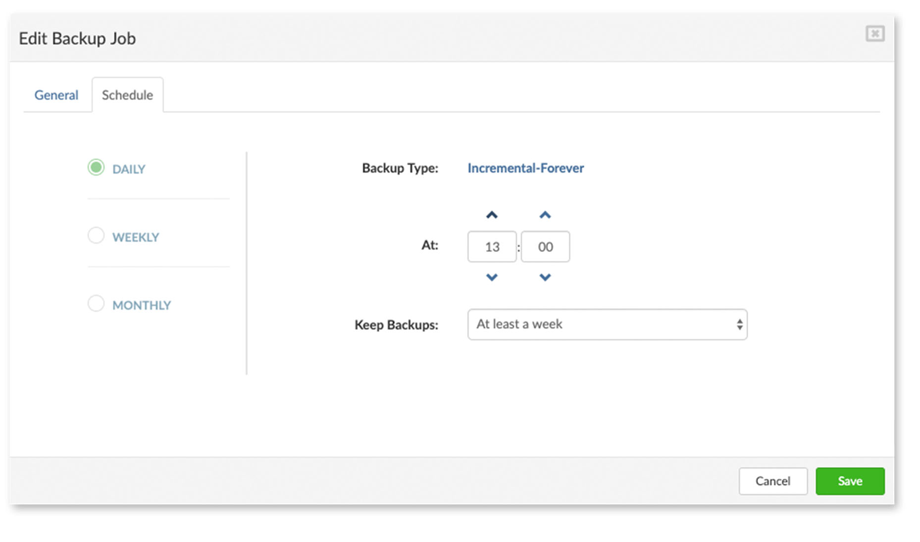
Schedule
Backup Type Select either a full or incremental backup job type.(If backup to zfs option selected only incremental backup type is available) The full backup type means that a full backup will always be performed at a set time and frequency. The incremental backup means that a full backup will be performed only once a week while incremental backup will be performed on other days.
At: select the period of time in wich backup action will be performed
Keep Backup : select from a dropdown of available retention time for backups
¶ Removing Backup Job
When removing a backup job, it is important to note that this action will not remove already created restore points, created by that backup job.
Follow this procedure to remove a backup job:
¶ VPS Restore from Browse & Restore menu
VPS restoration will revert a VPS to a previously saved restore point. Restore VPS option in Browse & Restore menu will create a new copy of a VPS. Follow this procedure to restore a VPS:
In the Backup menu select Browse & Restore submenu item.
From the Select a Backup Host menu select backup host which contains a backup set.

From Select a Backup set select a backup set which contains restore points fro VPS you want to restore.

Select VPS which you want to restore and click Restore button.
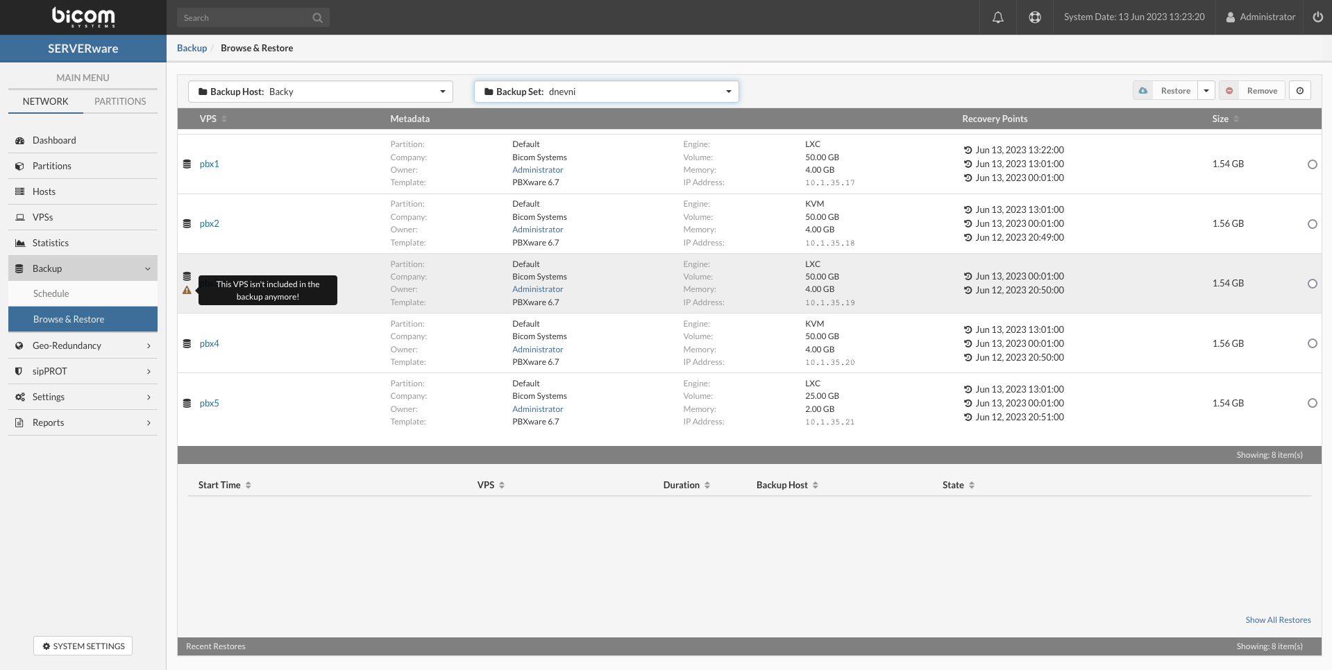
Select a restore point and destination partition to restore VPS and click Restore button.
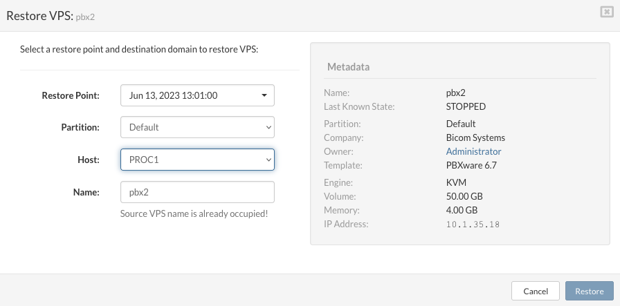
Restore of VPS will start and progress indicator bar will show progress in percentage and if necessary you can cancel restore by clicking on red Cancel icon on the right. Canceling restore will automatically delete VPS that is created by restore process and clean all data related to that restore process.
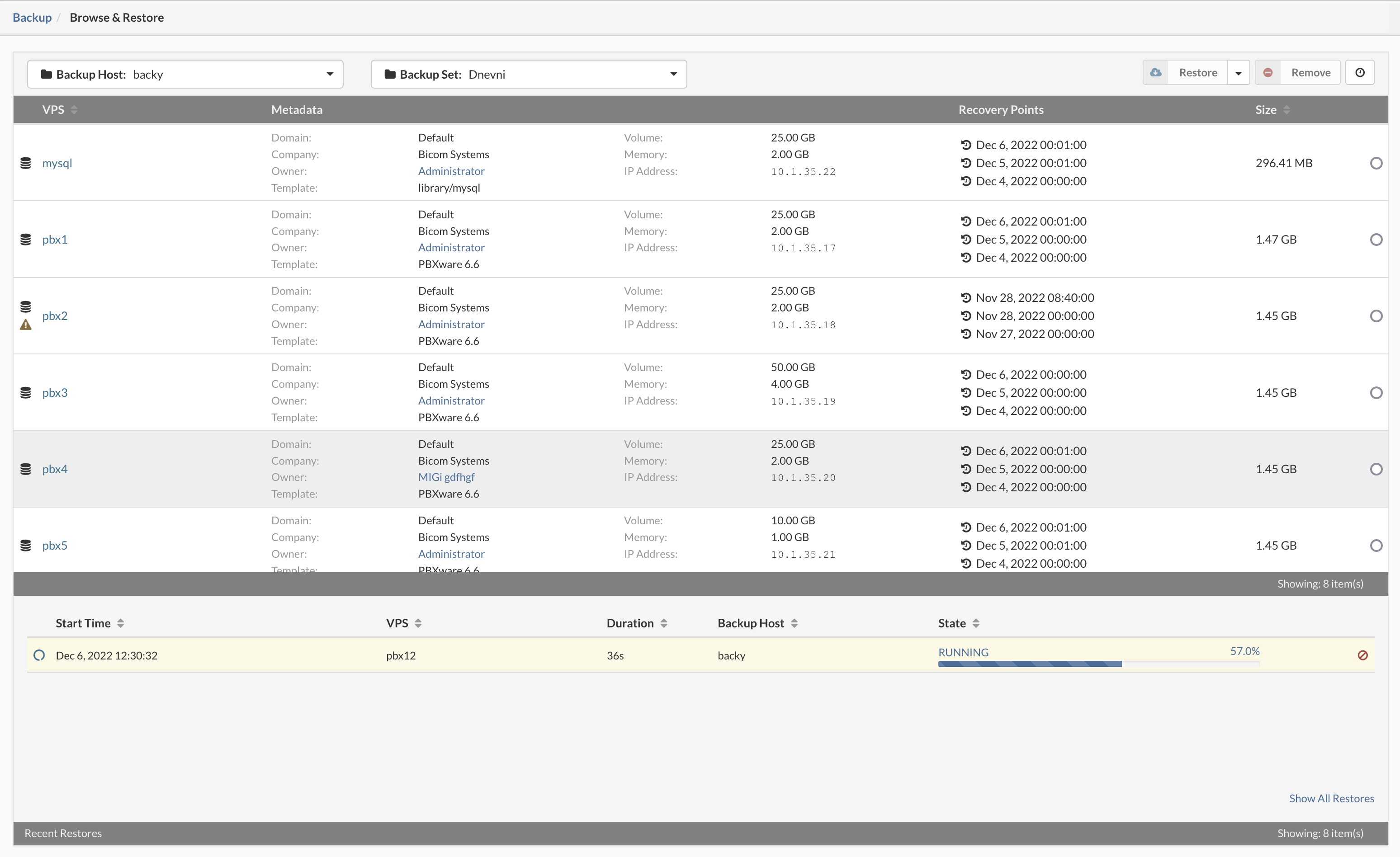
After completing restore process, Recent Restores view should look like below, now you can start using restored VPS.

¶ VPS Bulk Restore from Browse & Restore menu
VPS restoration will revert a VPS to a previously saved restore point. Bulk Restore VPSes option in Browse & Restore menu will create a new copys of selected VPSes. Follow this procedure to restore multiple VPSes (bulk restore):
In the Backup menu select Browse & Restore submenu item.
From the Select a Backup Host menu select backup host which contains a backup set.

From Select a Backup set select a backup set which contains restore points fro VPS you want to restore.

In upper right corner next to the Restore button click on Bulk Restore.
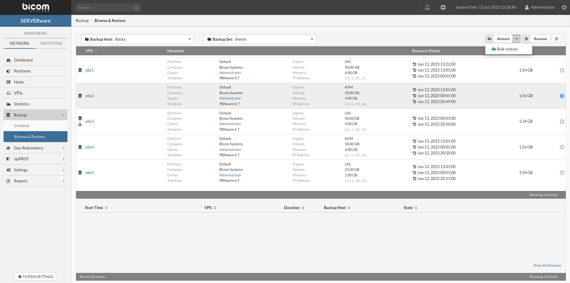
Initialize a queue of VPSes for the bulk restore action by configuring the restore options for an individual VPSes and adding them into the queue and click Start' button to start VPS bulk restore process
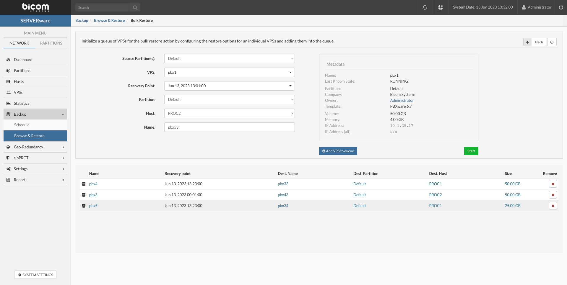
To see current running bulk restore task, in the Backup menu select Browse & Restore submenu item. Then select backup host on which bulk restore job is created.
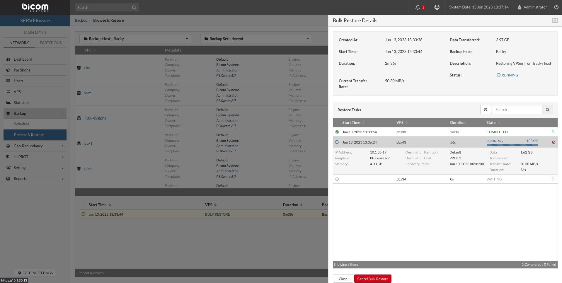
¶ Remove backup for VPS
From SERVERware 4.4 version, it is possible to permanently remove the backup and exclude the VPS from future backups. This feature is helpful if VPS is removed or backup for that VPS is no longer needed.
To remove VPS from the backup, go to the Backup section, then to Browse & restore. Select the Backup host and the Backup Set on which VPS is backed-up. Select the VPS and then click the Remove button in the upper right corner.
The popup dialogue will appear which can be selected to exclude VPS from future backups if needed.
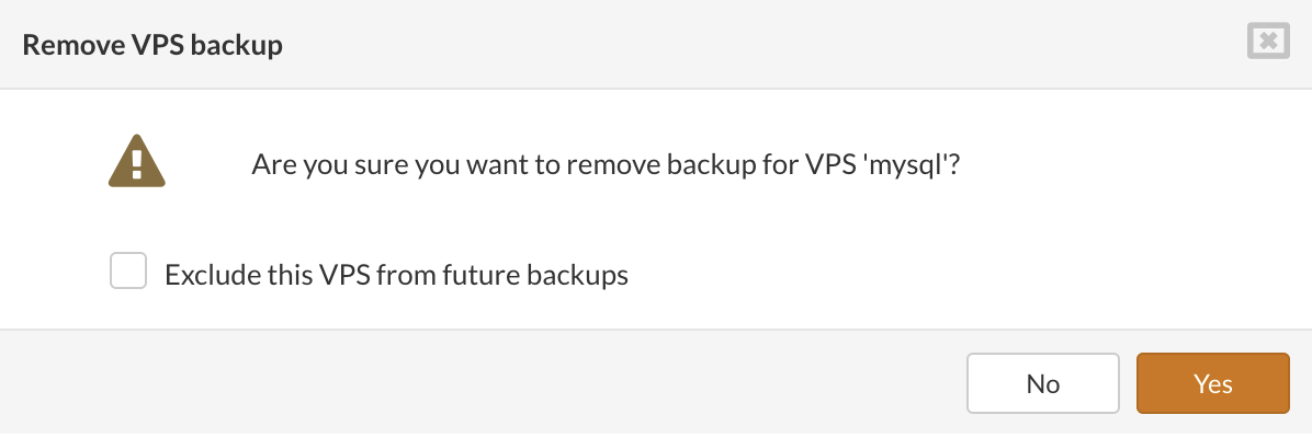
¶ Geo-Redundancy
There are two types of replication,in SERVERware.
Local Replication - By using the replication feature users can connect SERVERware on the same locations to replicate VPSs and be able to recover/takeover/move VPSs between multiple SERVERware instances or clusters with minimum data loss.
Geo-Redundancy - Equivalent to previous except to allow connection between multiple sites. In this case, SERVERware operating at two or more geographical locations as a redundancy in case the primary system fails due to any reason.
This feature will provide the user with the ability to take over services on a remote site with a certain degree of data shift, but that will primarily depend on how frequent data replication is between sites. However, the feature is to give more flexibility in infrastructure requirements, and lower the cost for the customer while still providing a tool on the computer platform level toward achieving a high percentage of availability.
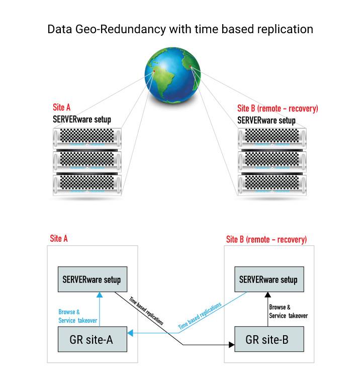
Once GRS (Geo-Redundancy Server) is connected with SERVERware, it can be used for two primary functions. One is to set up replication to this server, and another to browse/list existing replications with the option to select and takeover VPSs from.
Summary of properties
Configure the replication cycle
Browse & Takeover from GRS
Control GRS Resources
¶ Configure the replication cycle
For Geo-Redundancy feature to work license must be upgraded (please contact your account manager).
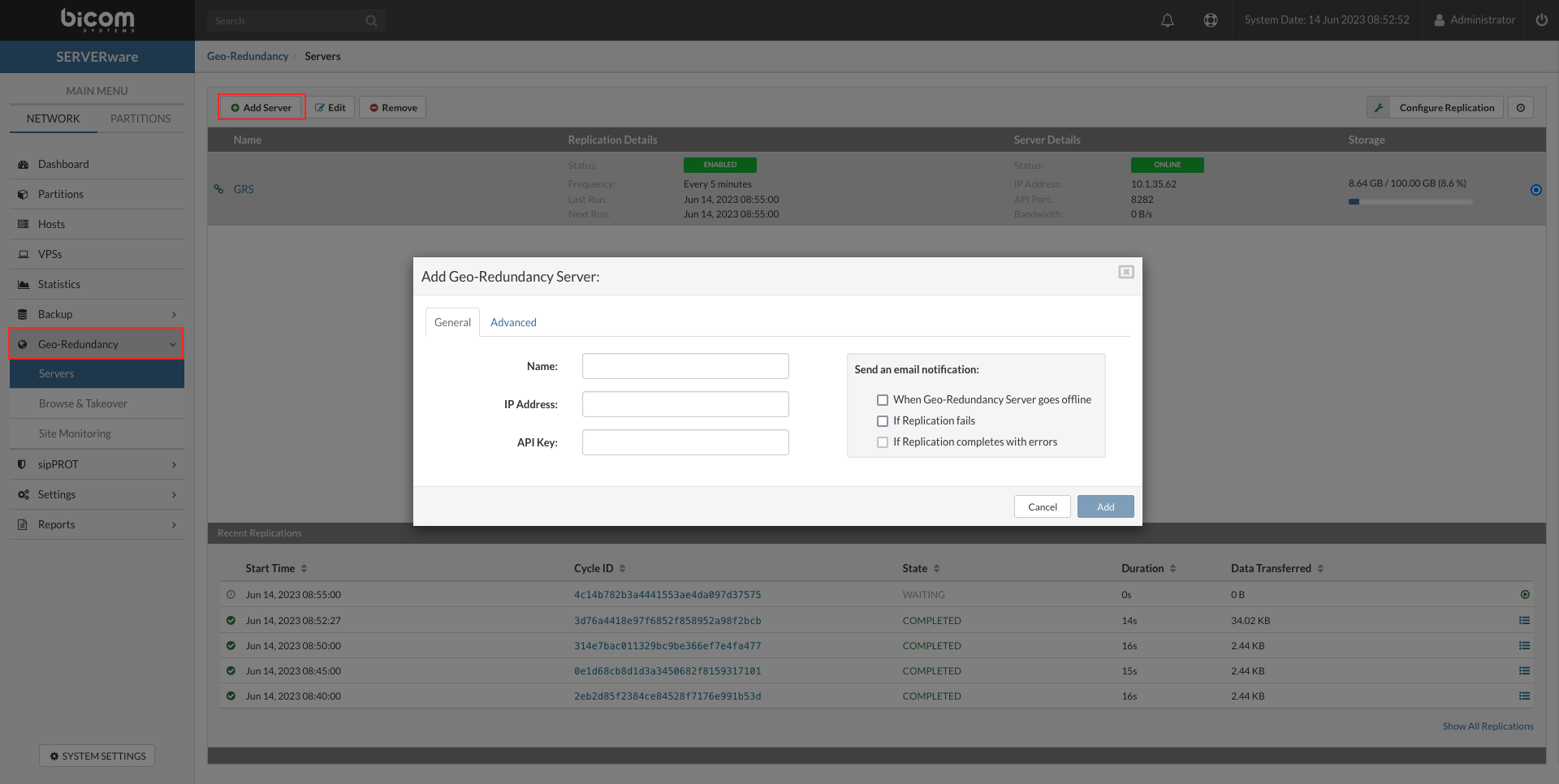
From the left menu, select Geo-Redundancy than from the drop down select Servers.
The Geo-Redundancy overview window will open.
To add the Geo-Redundancy Server press the Add server button in the upper left corner and a popup will open.
Enter new GRS details as required.
General
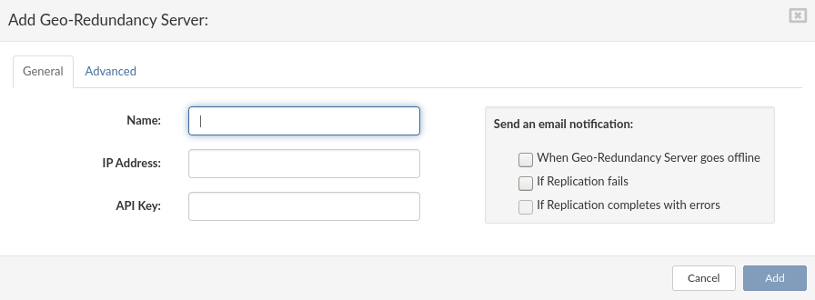
Advanced
Dropdown values
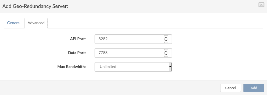
Populate all the required fields and press "Add".
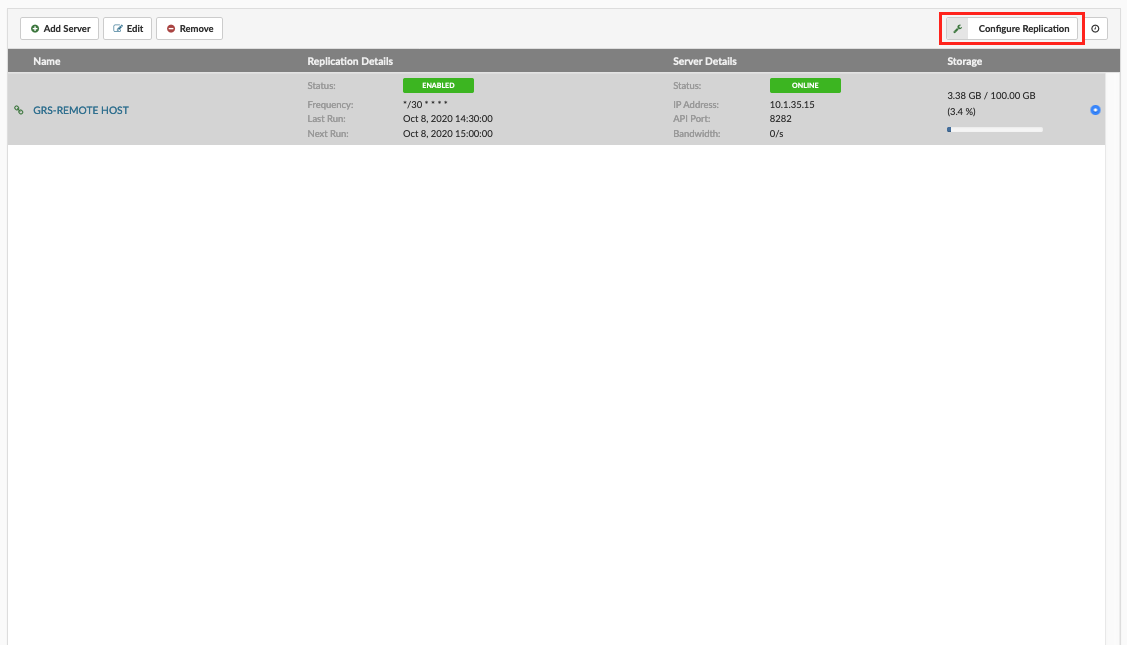
We have finished adding a new Replication site, now we can manage details for the Replication. Select the site you need to manage and press "Configure Replication" upper right corner.
Replication Config
Geo-Redundancy Server will keep replications until next full circle.
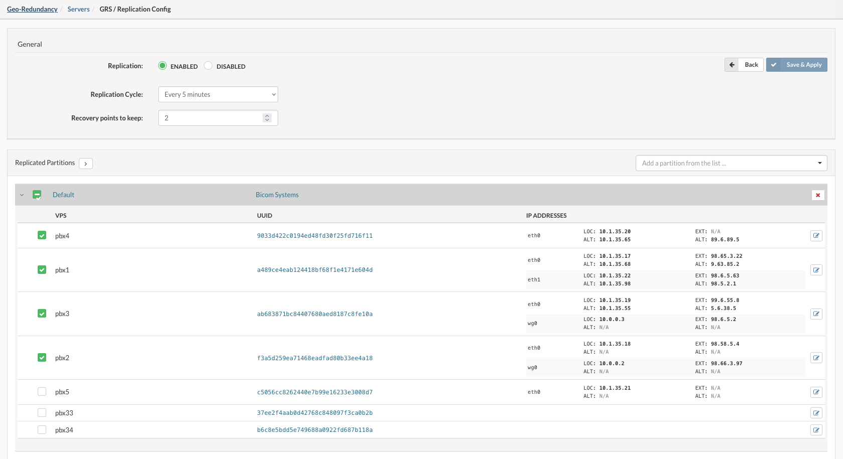
Replicated Partitions
The first replication will start depending on the time frame defined in configuration and it will be the "Full Replication Cycle" for every VPS selected.
Full replication is done only in the first cycle and can generate a high amount of traffic through the LAN network and cause a slow response while running, full replication should be planned when most VPSs are idle or stopped.
For GR sites that have more intricate networking, with multiple network cards and network interfaces assigned to hosts and VPSs, SW administrators can now assign multiple alternate IPs for each network interface added to a VPS.
Recent replications
Recent replications window display progress and status of replication cycles.

On the right side of every cycle, there is a detail view button, marked with the red square on the screenshot, when opened replication details will be displayed.
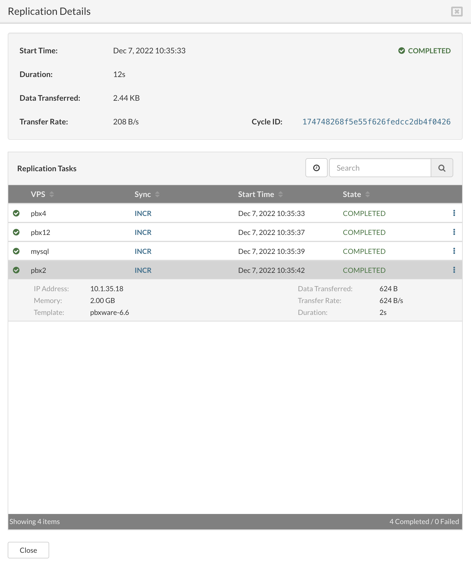
Replication Details
Replication tasks
¶ Browse & Takeover from Geo-Redundancy
SERVERware GR feature allows us to use multiple sites for replication purposes, the same data can be transferred to several locations to assure data loss prevention.
The replication configuration panel shows the list of remote sites (Geo-Redundancy Servers), and it will allow the configuration of scheduled replication per each. The number of Geo-Redundancy Servers is limited by license, and so implicitly a number of takeover sites. Adding more sites will require a license update.
The procedure of adding the GR site to the takeover location is the same as adding the GR site to the primary site location.
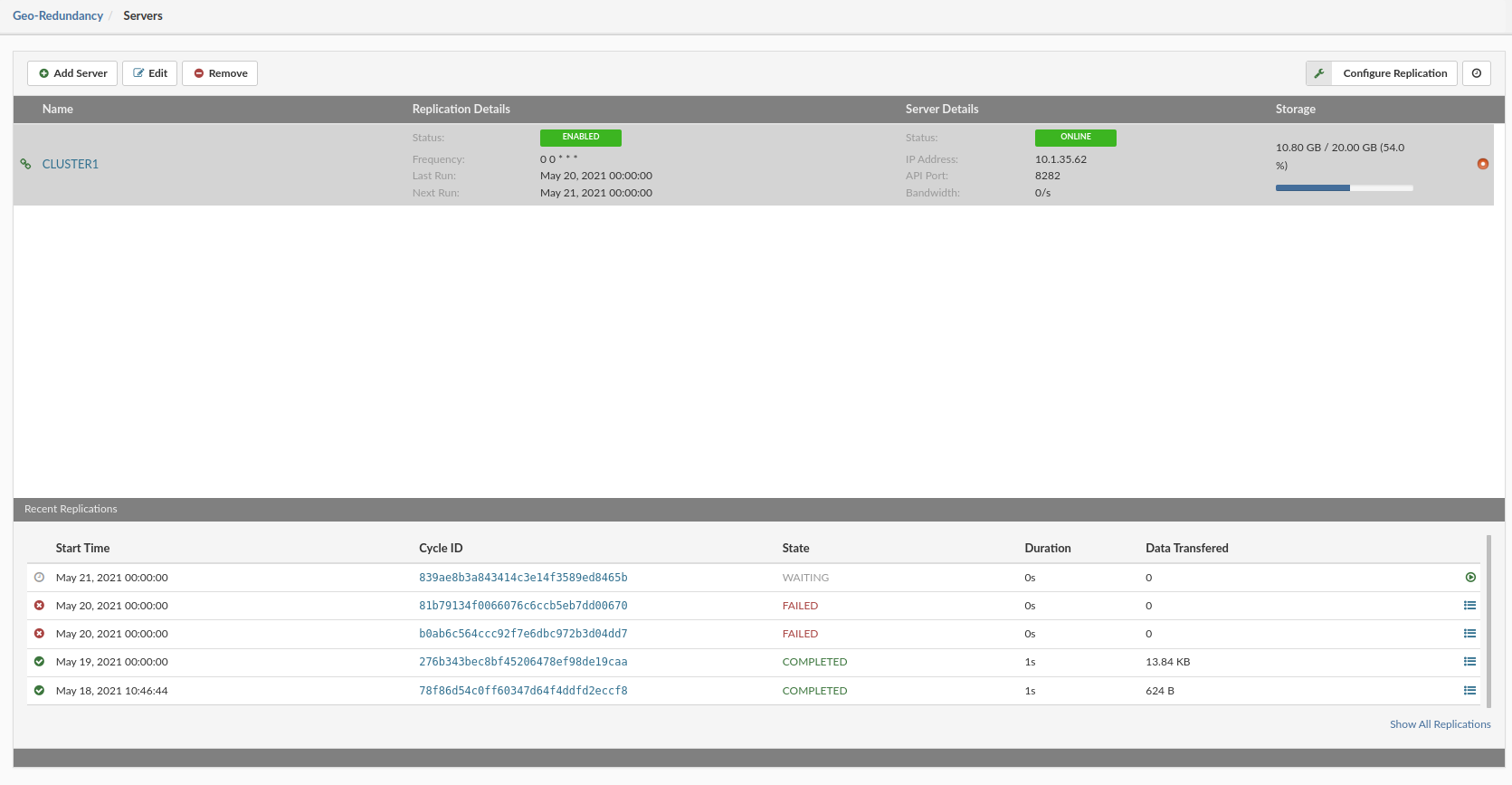
From the left menu, select Geo-Redundancy than from the drop down select **Servers''.
Geo-Redundancy Server overview will open.
To add the Geo-Redundancy Server press the Add server button in the upper left corner and a popup will open.
Enter new Geo-Redundancy Server details as required.
General
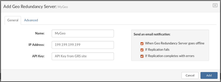
Advanced
Dropdown values
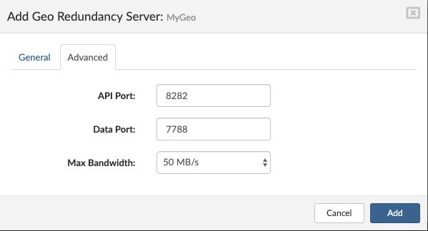
Populate all the required fields and press "Add".
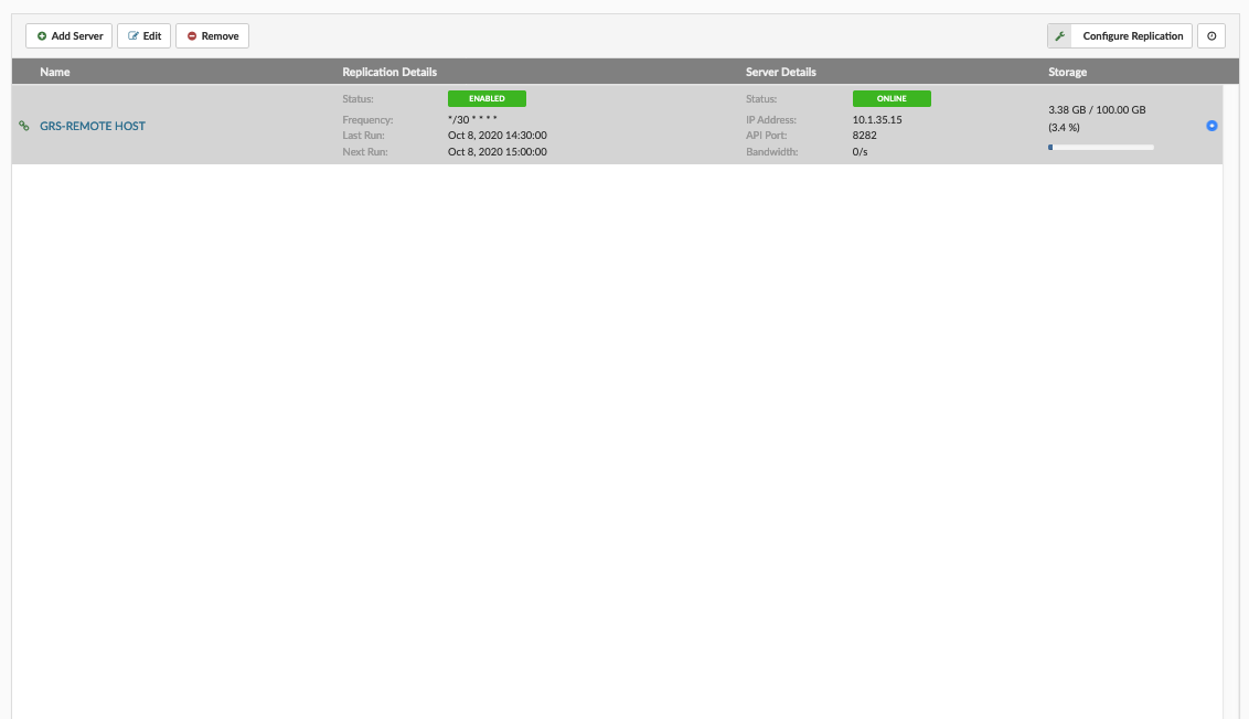
We have finished adding a replication site, now we can browse the replications.
Select the "Browse & Takeover" from the menu.
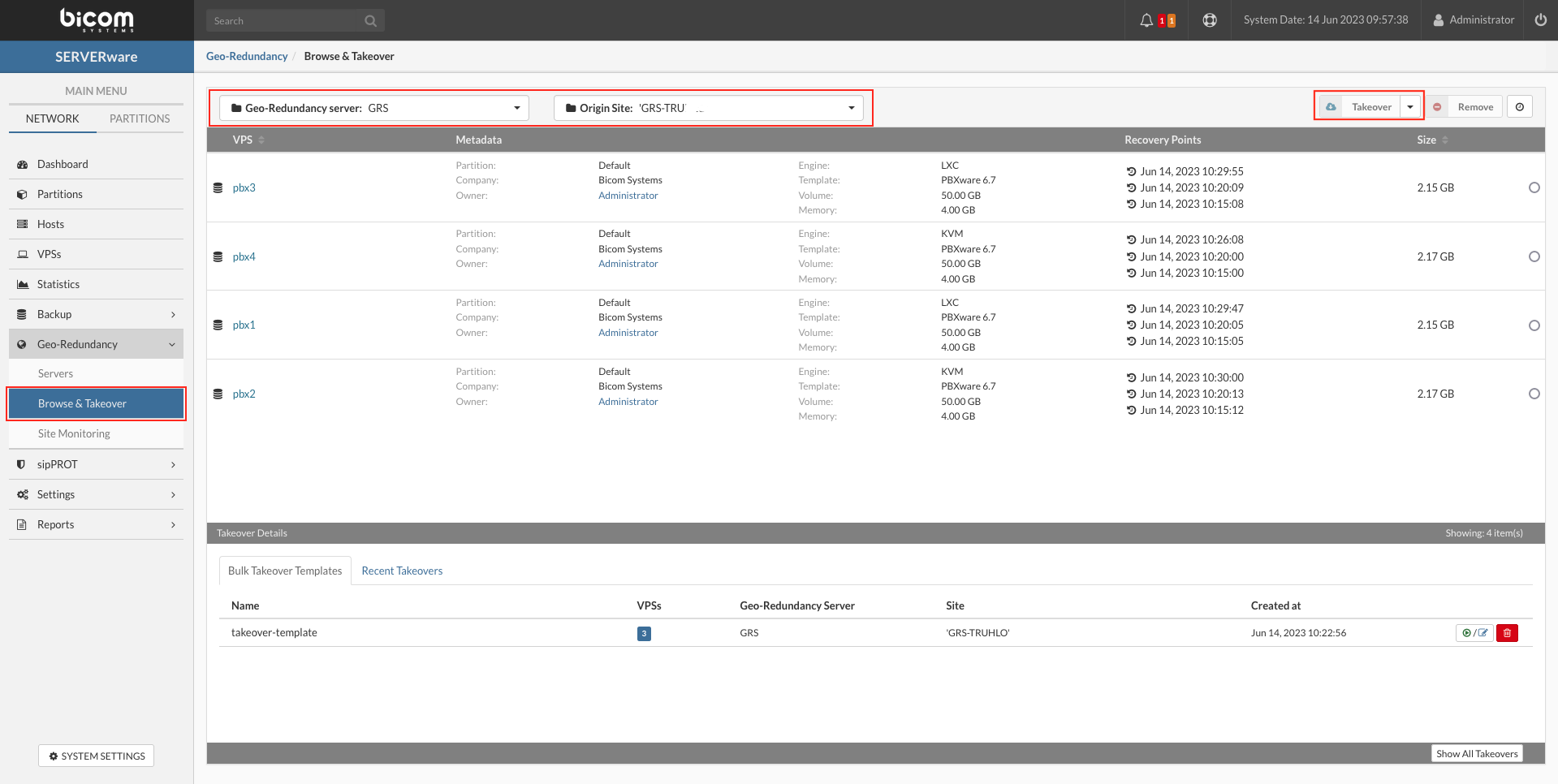
When the "Browse & Takeover" is open, in the upper left corner we can choose the Geo-Redundancy Server and Origin SIte after we choose this the list of the available replications will be displayed below.
Browse the replications, find and select the one you need to take over, and press the Takeover button in the upper right corner for a single VPS takeover or Bulk takeover for multiple VPS takeover.
Also, Bulk takeover action can be saved as Template for quick use in case of a primary site failure (templates can be edited/updated after the creation).
Takeover single VPS
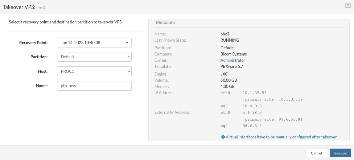
On the right side of the window Metadata of the VPS is displayed for the information purpose.
Metadata
Name: VPS-01
Last Known State: STOPPED
Partition: Default
Company:
Owner: Administrator
Template: PBXware 5.2
Engine: KVM
Volume: 41.00 GB
Memory: 2.00 GB
IP Address: 192.168.200.149
External IP Address: N/A
For virtual interfaces, post takeover the IPs would need to be manually set. Once the VPS has been taken over to the GR site, the alternate IPs will be automatically assigned. This goes for systems behind NAT, post-takeover, both local and external IP addresses will be automatically added to the VPS.
When fields are populated press the Takeover button in the right bottom corner
The takeover process will begin and the duration of the takeover depends on the amount of storage used by the selected VPS.
Bulk Takeover
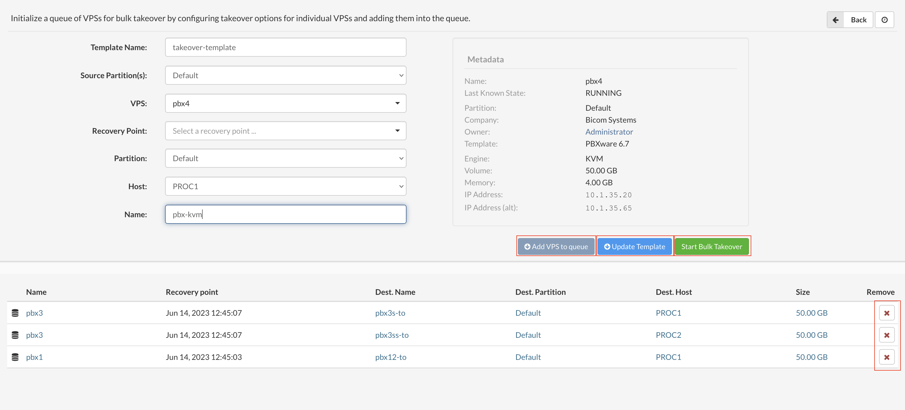
In the new Bulk takeover window user can add the VPSs to a takeover action with the series of steps:
When all fields are populated press add VPS to queue to add VPS to the list below, this action can be repeated for all VPSs in the Replication database.
When we have finished the list we have two options:
Saved templates window is the list of all saved templates on the server, here we can edit templates and delete templates.
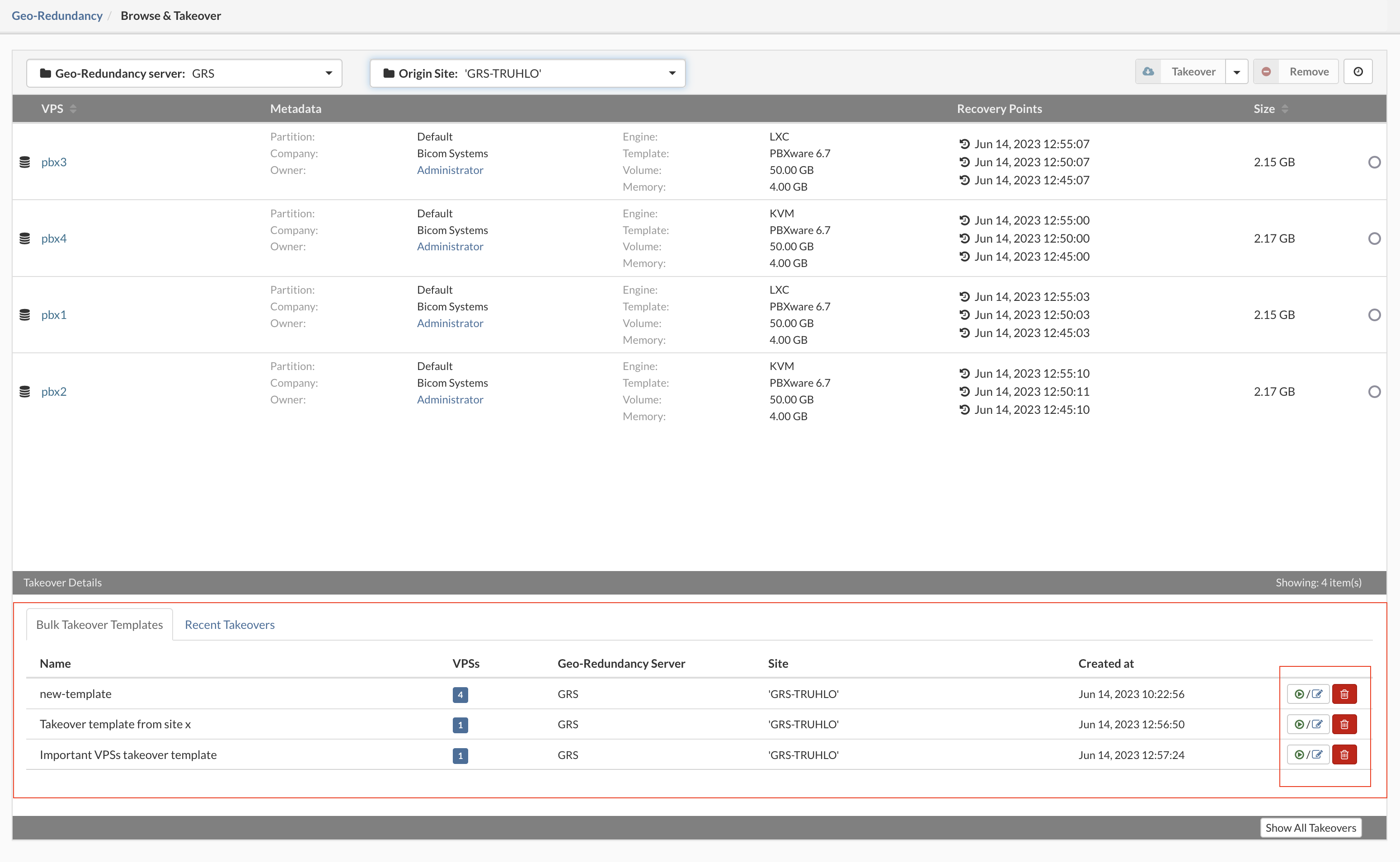
If started the takeover process details can be monitored in the Recent Takeovers window

During the takeover process it is possible to cancel single/multiple VPS takeover or to cancel all takeover with one click.
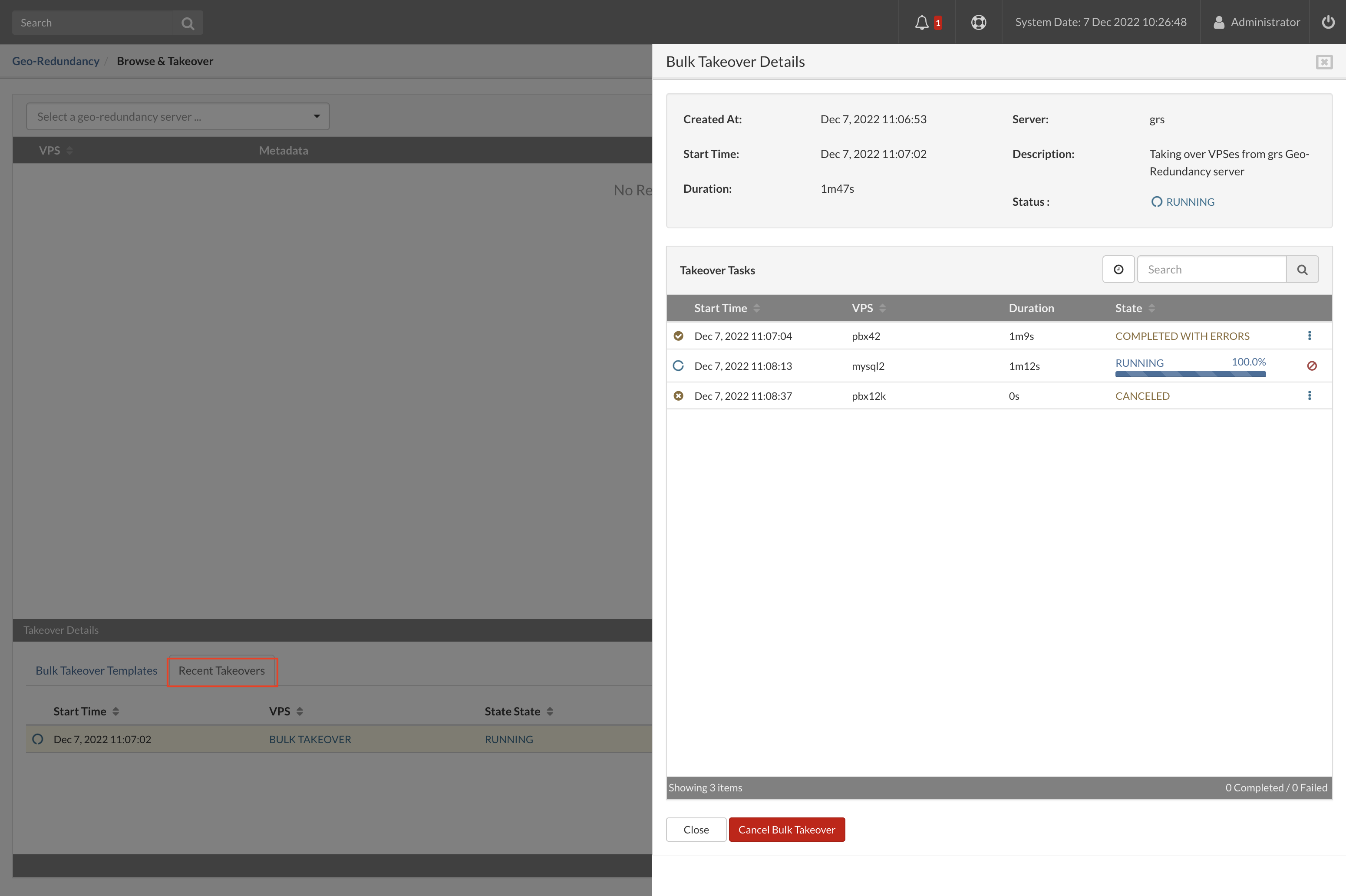
When the Takeover process is COMPLETED, VPS can be managed from the VPSs section on the main menu.
This concludes take over process.
¶ Remove replicated VPSs
SERVERware administrators are able to remove old or unnecessary VPS replications from the GR pool by simply selecting the replication they wish to remove and then clicking on the remove button. This will in no way affect the VPS on the production site, or have any impact on the VPSs that are running on the GR site. Once the VPS is removed from the GR pool, it can easily be replicated in full in the next replication cycle.
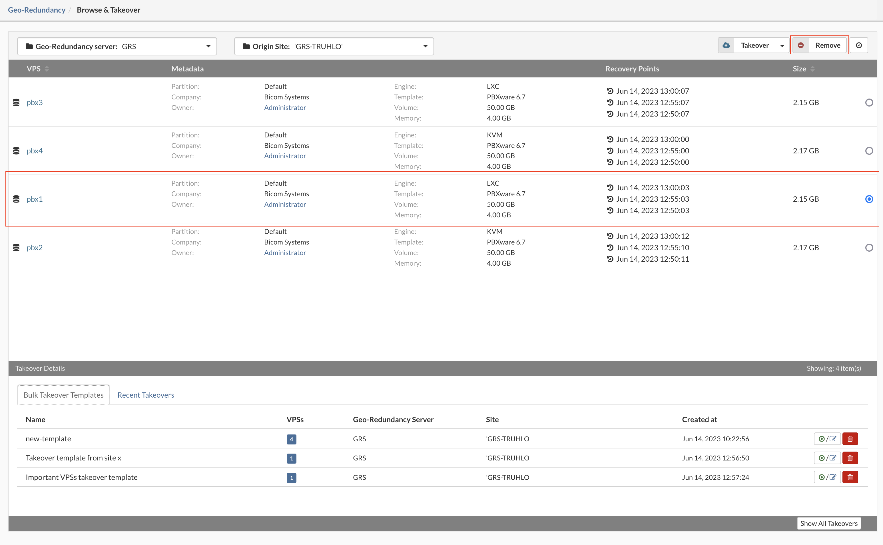
To remove VPS replication, select the VPS and click on the Remove button. Pop-up dialoge will appear to confirm removal.

For replications older than two weeks, the administrator will see a warning icon indicating that the snapshot in question has data that hasn’t been resynced for the above mentioned time frame.
¶ Geo-Redundancy / Site Monitoring
Site monitoring enables the SERVERware administrator to setup monitoring of remote sites by creating a set of tests that will report whether the monitored site is available or not. The administrator can add actions that will be executed in case tests fail. Actions can be configured to trigger only if all tests fail **(ALL action type)** and if any of the tests fail **(ANY action type)**.
The main function of the site monitor is to monitor the replication site with a series of different tests and execute actions based on the test results.
To create and start site monitoring select the Site monitoring from the Replication menu.
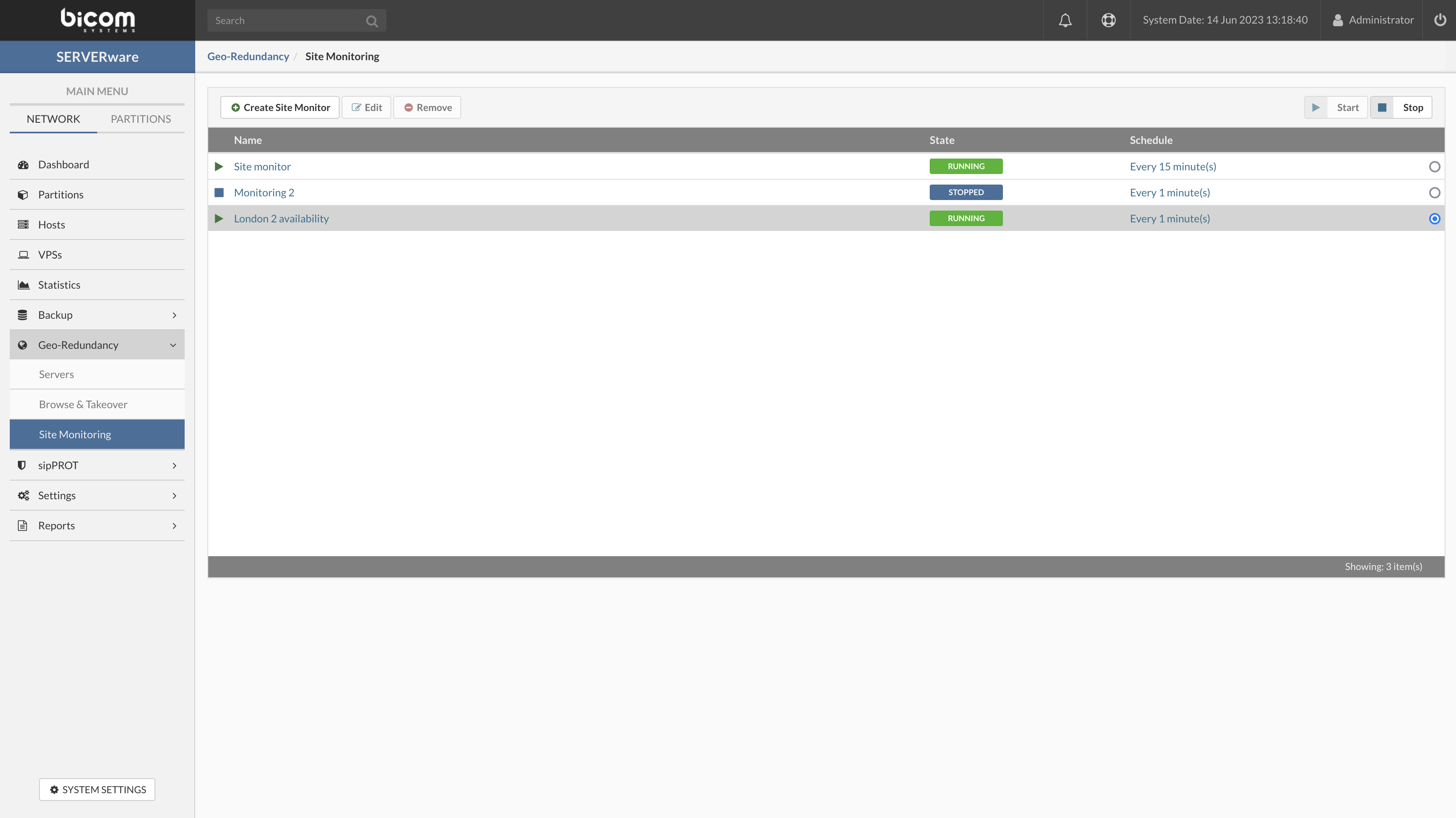
| Field | Description |
|---|---|
| Destination: | This will be destination for our ICMP test, set the "IP address" or "Partition name" as destination. |
| Packet count: | Specifies the number of echo requests, or pings, to be sent. |
| Test Timeout (s): | Designates the maximum amount of time for the test duration. After that time, test will stop. |
| Packet delay(ms): | Delay between pings designates the time in milliseconds between each successive PING to the target address. Setting this value very low will send a constant stream of Pings to the destination IP address. |
| TTL: | Designates the number of hops allowed along the way to the specified address. With a setting of 10, your PING test could pass through up to 10 different routers on the way to the remote address before being discarded by the network. |
| Packet size(B): | Designates the number of data bytes to be sent. The default is 64, combined packet size 56 bytes with the 8 bytes of ICMP header data. |
| Maximum loss (%): | Designates the maximum acceptable amount of "packet Loss" in percents(%). |
| Max avg. latency (ms): | Designates the maximum acceptable amount of "average latency" in milliseconds. ''If the latency is above entered value test will fail''. |
| Timed out: | When ON it will ignore field Test Timeout. |
| Invert result: | When ON it will invert test results, ''A failed test will be successful and vice versa''. |
| Dry Run button | When pressed will run the "dry test" and display results.(for successful test will be "GREEN" info bar, and fail test will be "RED" info bar). |
| Cancel button | Will discard all changes and close the dialogue. |
| Update | Will update test configuration and close the dialogue. |
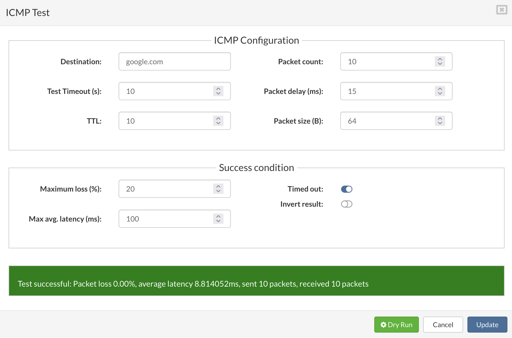
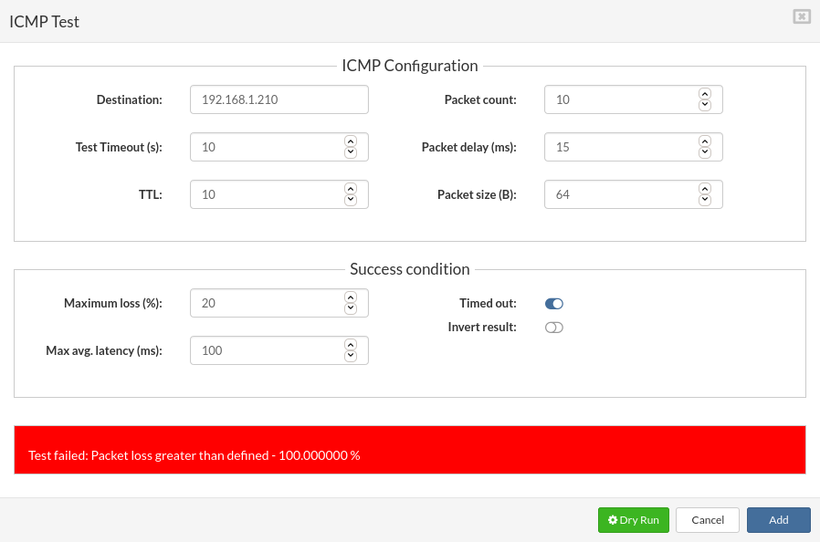
The HTTP test use standard GET, HEAD, POST, PUT, DELETE, requests set and additional success conditions.
The Hypertext Transfer Protocol (HTTP) is designed to enable communications between clients and servers.
HTTP works as a request-response protocol between a client and server.
Example: A client(our test) sends an HTTP request to the server; then the server returns a response. The response contains status information about the request and may also contain the requested content.
| Field | Description |
|---|---|
| URL: | This will be destination for our HTTP test, "http://", or "https://" are mandatory in destination address. |
| Request Type: | * The HTTP GET method requests a representation of the specified resource. Requests using GET should only be used to request data (they shouldn't incude data). * The HTTP HEAD method requests the headers from requested url. * The HTTP POST method sends data to the server. The type of the body of the request is indicated by the Content-Type header. * The HTTP PUT request method creates a new resource or replaces a representation of the target resource with the request payload. * The HTTP DELETE request method deletes the specified resource. |
| Test Timeout (s): | Designates the maximum amount of time for the test duration. After that time, test will stop. |
| Verify SSL: | You can verify the SSL certificate on your destination to make sure it is correctly installed, valid, trusted and doesn't give any errors to any of your users |
| Headers | HTTP headers let the test server pass additional information with an HTTP request or response. An HTTP header consists of its Name and Value * Example: ** Name: Authorization ** Value: Basic U0VSVkVSd2FyZTpleGFtcGxl  |
| Arguments: | HTTP Arguments let the test server pass specific arguments with an HTTP request or response. An HTTP argument consists of its Name and Value * Example: ** GET from: https://www.google.com/search ** Name: q ** Value: SERVERware 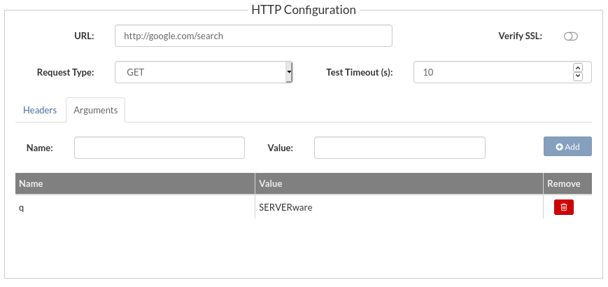 |
| Body: | Body is used to manually add body for your request, depending of your needs. * Body in JSON example: { "name": SERVERware, "version":4 } |
| Response Code: | HTTP response status codes indicate whether a specific HTTP request has been successfully completed. The test will fail if the requested code is not returned from the destination. Responses are grouped in five classes: Informational responses (100–199) Successful responses (200–299) Redirects (300–399) Client errors (400–499) Server errors (500–599) More details on response codes: ''https://developer.mozilla.org/en-US/docs/Web/HTTP/Status'' |
| Response RegExp: | Regular expression is used for parsing the response code. Example:  In the test above if the test response contains SERVERware the test will pass. More details on how to use regular expressions: https://en.wikipedia.org/wiki/Regular_expression |
| Invert result: | When ON it will invert test results, ''A failed test will be successful and vice versa''. |
| Dry Run button | When pressed will run the "dry test" and display results.(for successful test will be "GREEN" info bar, and fail test will be "RED" info bar). |
| Cancel button | Will discard all changes and close the dialogue. |
| Update | Will update test configuration and close the dialogue. |
''The Transmission Control Protocol(TCP) is a transport protocol carried over the Internet Protocol(IP). Together the two protocols are often called the TCP/IP protocol stack. The TCP is a host-to-host protocol it's scope is to provide reliable process-to-process communication in a multinetwork environment. Where IP provides no guarantee that sent packets are actually delivered to the intended recipient in the right order, TCP detects these problems, re-transmits lost data, removes duplicated data, and rearranges out-of-order data. Hereby TCP provides reliable, ordered and error-checked data delivery between applications communicating through an IP network.''
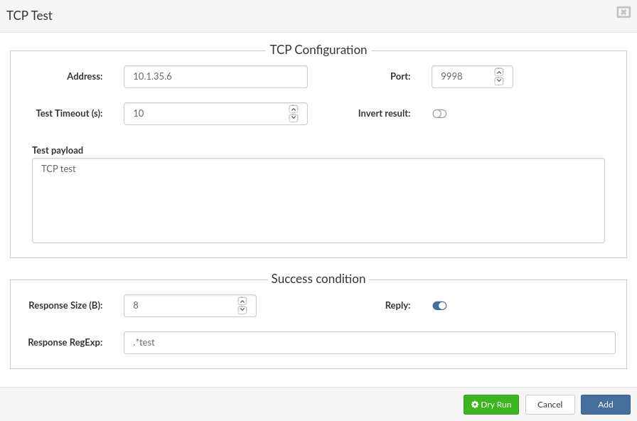
| Field | Description |
|---|---|
| Address: | This will be destination IP address for our TCP test. |
| Port: | Specifies the target port. |
| Test Timeout (s): | Designates the maximum amount of time for the test duration. After that time, test will stop. |
| Invert result: | When ON it will invert test results, A failed test will be successful and vice versa. |
| Test payload | The payload of a TCP or UDP packet is the data portion of the packet. |
| Response Size(B): | Expected size in Bytes of the response payload. If the response payload returns the correct response size, the test success condition is met. |
| Response RegExp: | Regular expression is used for parsing the response code. More details on how to use regular expressions: https://en.wikipedia.org/wiki/Regular_expression |
| Reply: | When ON success condition parameters will be used in the test. |
| Dry Run button | When pressed will run the "dry test" and display results.(for successful test will be "GREEN" info bar, and fail test will be "RED" info bar). |
| Cancel button | Will discard all changes and close the dialogue. |
| Add / Update | Will add / update test configuration and close the dialogue. |
''The User Datagram Protocol (UDP) is a connectionless transport-layer protocol (Layer 4) that belongs to the Internet protocol family. UDP is basically an interface between IP and upper-layer processes. UDP protocol ports distinguish multiple applications running on a single device from one another. Unlike the TCP, UDP adds no reliability, flow-control, or error-recovery functions to IP. Because of UDP’s simplicity, UDP headers contain fewer bytes and consume less network overhead than TCP. UDP is useful in situations where the reliability mechanisms of TCP are not necessary, such as in cases where a higher-layer protocol might provide error and flow control. UDP is the transport protocol for several well-known application-layer protocols, including Network File System (NFS), Simple Network Management Protocol (SNMP), Partition Name System (DNS), and Trivial File Transfer Protocol (TFTP).''
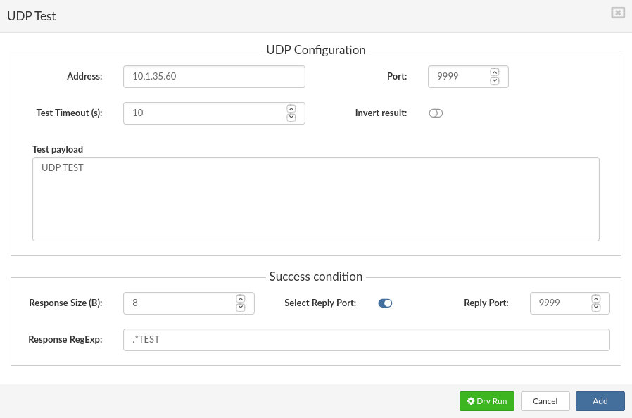
| Field | Description |
|---|---|
| Address: | This will be destination IP address for our TCP test. |
| Port: | Specifies the target port. |
| Test Timeout (s): | Designates the maximum amount of time for the test duration. After that time, test will stop. |
| Invert result: | When ON it will invert test results, ''A failed test will be successful and vice versa''. |
| Test payload | The payload of a UDP packet is the data portion of the packet. |
| Response Size(B): | Expected size in Bytes of the response payload. If the response payload returns the correct response size, the test success condition is met. |
| Response RegExp: | Regular expression is used for parsing the response code. More details on how to use regular expressions: ''https://en.wikipedia.org/wiki/Regular_expression'' |
| Select Reply Port: | When ON success condition parameters (reply port) will be used in the test. |
| Dry Run button | When pressed will run the "dry test" and display results.(for successful test will be "GREEN" info bar, and fail test will be "RED" info bar). |
| Cancel button | Will discard all changes and close the dialogue. |
| Add / Update | Will add / update test configuration and close the dialogue. |
M/Monit uses Monit as an agent and can manage and monitor all your hosts and services. SERVERware 4.3.x version comes with integrated MMonit which can be used for monitoring systems from SERVERware.
A New MMonit option in the 'Add Site Test' dropdown list is added for easier setup of SERVERware Site monitoring with the third part monitoring tool “MMONIT”.
In the Site Monitoring Name field enter the desired Name for the monitor (In the example we will use the MMONIT ). Set the Schedule time [this represents the time, how often the test will be triggered] and press Save and Apply.
Next, we need to add a New site Test (from the dropdown select MMonit).
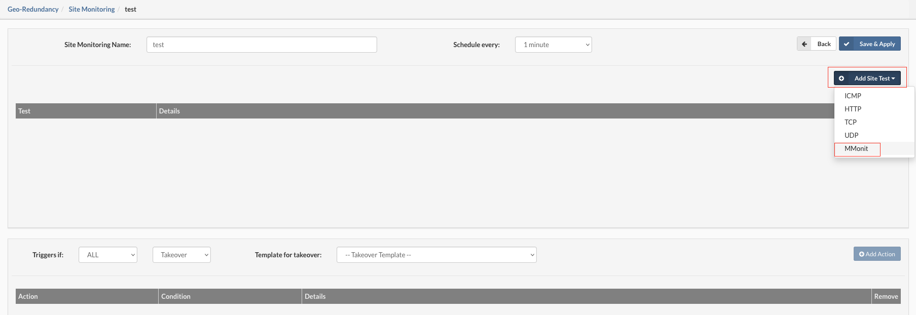
A popup window will appear:
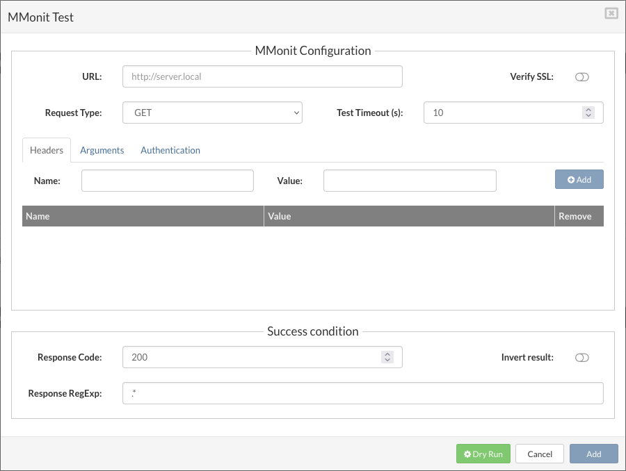
Populate the fields:
URL: http:// < MMONIT IP > :8080/api/1/reports/events/list
Request Type: GET (Per MMonit API documentation)
Test Timeout in seconds: 10 [test will wait for the response max 10 seconds after this if no response test will fail]
Per MMonit API documentation we need to add two arguments in our API call to filter only fail events
First, on the Arguments tab, we will add
z_csrf_protection with value off
and
state with the value 1 (this will filter results and display only fail events)
In the Authentication, tab enter the username and the password for the MMonit (this is the user and the pass from the GUI )
For the success conditions, we will use
Response code: 200 [default]
Response RegExp: (we will search for the hostname we have set in the MMonit earlier)
Now we can test our setup by pressing the "Dry Run" button the result should be Test successful (at this point make sure your MMonit is not failing already).
Press the Update button and the test will be saved in the test list.

Test can be edited/removed with the click on the appropriate icon. Actions can be removed only.
¶ Control Geo-Redundancy Server Resources
Geo-Redundancy Server has its own setup and configuration for its services. Authentication and authorization of access to this service will be determined by API keys and Access Control Lists (ACL). There are two distinct use cases:
To manage the replication service we will be using a tool called "swrepl-adm", this is a CLI managed tool.
Open the SSH client (Putty for example which can be downloaded from http://www.chiark.greenend.org.uk/~sgtatham/putty/download.html).
Under 'Host Name', type the host system IP address (e.g. 232.123.44.108).
Set 'Port' # '2222'. Click on the 'Open' button to initialize the connection.
Default login for your ssh connection will be “root” and password: “serverware”.
Once you have logged in on your server, you can start using CLI commands.
IMPORTANT If deployed on the mirror/cluster setup of storage servers, we will use “floating IP” from, that way ssh client will connect you to whatever server is in the primary state. Replication storage must be located on the storage host in the NETSTOR pool. Storage for the Geo-Redundancy Server should only be considered as a pool with SSD storage.
After logging, on the screen, you should get simple output information about the server.
Example :
  ███████╗██╗    ██╗      ██╗  ██╗
 ██╔════╝██║    ██║      ██║  ██║
 ███████╗██║ █╗ ██║█████╗███████║
 ╚════██║██║███╗██║╚════╝╚════██║
 ███████║╚███╔███╔╝           ██║
 ╚══════╝ ╚══╝╚══╝            ╚═╝

 * SERVERware system IP Address/es:
 * 127.0.0.1/x 192.168.x.x/x 10.1.x.x/x 192.168.x.x/x


 * Login into the setup by visiting:
 * https://127.0.0.1:81/
 * https://192.168.x.x:81/
 * https://10.1.x.x:81/
 * https://192.168.x.x:81/

 ~ #
Start using the SWREPL application by running the command :
~ # swrepl-adm
The swrepl-adm console will be opened in the terminal and we can start creating a site for replication.
¶ The list of commands supported
site { COMMAND | help}
COMMAND :#
Add replication site with description, optional set storage quota, throttling in bytes per second,
and allowed IPs (default allows all).
e.g. "192.168.1.10, 10.1.0.0/16, 2001:db8:a0b:12f0::1/32"
default value 0.0.0.0/0 in the list means allow all
Update replication site with description, optional set storage quota, throttling in bytes per second,
and allowed ips (default allows all).
replication { COMMAND | help}
COMMAND :#
COMMAND :#
To be able to create a GRS site we must first create a ZFS dataset for this purpose.
The Geo-Redundancy dataset can be created on the storage host NETSTOR pool.
Minimum storage available for the Geo-Redundancy Server should be double the size of the initial storage occupied by the VPS's combined in the replication circle.
Storage for the Geo-Redundancy Server should only be considered as a pool with SSD storage.
ZFS file systems are created by using the zfs create command. The create subcommand takes a single argument: the name of the file system to be created. The file system name is specified as a pathname starting from the name of the pool as follows:
pool-name/[filesystem-name/]filesystem-name
The pool name and initial file system names in the path identify the location in the hierarchy where the new file system will be created. The last name in the path identifies the name of the file system to be created.
In the following example, a datase named GRS is created in the NETSTOR file system.
~ # zfs create NETSTOR/GRS
ZFS automatically mounts the newly created file system if it is created successfully. By default, file systems are mounted as /dataset, using the path provided for the file system name in the create subcommand. In this example, the newly created Geo-Redundancy Server file system is mounted at /NETSTOR/GRS.
Execute zfs list command to ensure dataset is created:
~ # zfs list
NAME                                                                                     USED  AVAIL  REFER  MOUNTPOINT
NETSTOR                                                                                  489G   156G   142M  /NETSTOR
NETSTOR/CONTROLLER                                                                      1.38G   156G  1.38G  /NETSTOR/CONTROLLER
NETSTOR/GRS                                                                              483G   156G   112K  /NETSTOR/GRS
NETSTOR/logs                                                                             476K  8.00G   476K  /NETSTOR/logs
NETSTOR/templates                                                                       3.60G   156G    96K  none
SYSTEM-e274                                                                             10.1G   205G    96K  none
SYSTEM-e274/BACKUP                                                                        96K   205G    96K  legacy
SYSTEM-e274/rootfs                                                                      6.63G  8.37G  4.63G  /
SYSTEM-e274/rootfs/log                                                                   118M  1.89G   118M  legacy
SYSTEM-e274/swap                                                                        2.13G   207G    60K  -
After this continue with creating the 8145EEE4 site.
On the selected host run swrepl-adm CLI tool.
~ # swrepl-adm
»
Space used for the Geo-Redundancy dataset should be 60% of the storage space available, this way we will secure there is enough space left for replications.
When in the "swrepl-adm" console we can use CLI commands to create a new site to do this we will type :
» site add -storage NETSTOR/GRS -quota 450G -throttle 70M  -admin=false  -allowedips "192.168.1.10,10.1.0.0/16"  "this is my site"
OK 93010f9f4003723d2eec317bf7160e0d
In the list of allowed IPs the remote Controller IP, and the Storage Host IP addresses must be allowed. The best practice is to add the whole subnet of the cluster.
The site with ID: 93010f9f4003723d2eec317bf7160e0d is created, to confirm the site parameters type:
» site list
      ID     |      INFO       | ADMIN |   STORAGE   |   QUOTA   | THROTTLING
+------------+-----------------+-------+-------------+-----------+------------+
  93010f9... | this is my site | false | NETSTOR/GRS | 450.0 GiB   | 70.0 MiB/s
+------------+-----------------+-------+-------------+-----------+------------+
All available sites will be displayed, for a more detailed view add site ID after the command
» site list 93010f9f4003723d2eec317bf7160e0d
    ID:          93010f9f4003723d2eec317bf7160e0d
    Description: this is my site
    Admin:       false
    API Key:     7e0f6463412acc17d3ff163065c1d897
    Storage:     NETSTOR/GRS
    Quota:       450.0 GiB
    Throttling:  70.0 MiB/s
    Allowed IPs: 192.168.1.10,10.1.0.0/16
to edit the site parameters after the creation site update command can be used:
lets change allowed IPs for example:
» site update 93010f9f4003723d2eec317bf7160e0d -allowedips 0.0.0.0
OK
» site list 93010f9f4003723d2eec317bf7160e0d
    ID:          93010f9f4003723d2eec317bf7160e0d
    Description: this is my site
    Admin:       false
    API Key:     7e0f6463412acc17d3ff163065c1d897
    Storage:     NETSTOR/GRS
    Quota:       450.0 GiB
    Throttling:  70.0 MiB/s
    Allowed IPs: 0.0.0.0
If the details on the site are correct we can use API Key: 7e0f6463412acc17d3ff163065c1d897 to connect the SERVERware to our newly created site and start the replication process.
If there is failure on primary site after failover and restore to remote location, to return data to primary site, using the same procedure we will create Geo-Redundancy dataset on storage host (Site - A) and return data to primary location.
¶ Geo-Redundancy dataset on the Processing/Backup host
To create a new dataset log-on the Processing Host
~ # zpool status | grep pool
pool: SYSTEM-e694
~ # zfs create SYSTEM-e694/GRS
~ # zfs set mountpoint=legacy SYSTEM-e694/GRS
~ # zfs set overlay=on SYSTEM-e694/GRS
~ # mkdir /GRS
~ # mount -t zfs SYSTEM-e694/GRS  /GRS
~ # cat /proc/mounts | grep GRS

SYSTEM-e694/GRS /GRS zfs rw,relatime,xattr,noacl 0 0
The output of the last command should be copied into /etc/fstab.
~# nano /etc/fstab

# /etc/fstab: static file system information.
#
# noatime turns off atimes for increased performance (atimes normally aren't
# needed); notail increases the performance of ReiserFS (at the expense of storage
# efficiency).  It's safe to drop the noatime options if you want and to
# switch between notail / tail freely.
#
# The root filesystem should have a pass number of either 0 or 1.
# All other filesystems should have a pass number of 0 or greater than 1.
#
# See the manpage fstab(5) for more information.
#

# <fs>                  <mountpoint>    <type>          <opts>          <dump/pass>

# NOTE: If your BOOT partition is ReiserFS, add the notail option to opts.
systemd                      /sys/fs/cgroup/systemd	  cgroup    rw,relatime,name#systemd  0 0

/dev/zvol/SYSTEM-e694/swap        none           swap	   defaults              0	0
SYSTEM-e694  /rootfs/log       /var/log       zfs       rw,relatime,xattr     0	   0
SYSTEM-e694/GRS /GRS zfs rw,relatime,xattr,noacl 0 0
After the editing saves the file and exit.
~ # zfs list
NAME                                                                                         USED  AVAIL  REFER  MOUNTPOINT
SYSTEM-e694                                                                                  117G   225G    19K  none
SYSTEM-e694/GRS                                                                               24K   225G    24K  legacy
SYSTEM-e694/rootfs                                                                          7.10G  7.90G  5.10G  legacy
SYSTEM-e694/rootfs-prev                                                                     4.94G  10.1G  4.94G  /
SYSTEM-e694/rootfs/log                                                                      24.9M  1.98G  24.9M  legacy
SYSTEM-e694/swap                                                                            2.13G   227G    12K  -
If we can see a new dataset as shown (SYSTEM-e694/GRS 24K 225G 24K legacy) we have successfully created a new dataset and we can continue setting up the Replication users.
On the selected host run swrepl-adm CLI tool.
~ # swrepl-adm
»
Space used for the Replication dataset should be 60% of the storage space, this way we will secure there is enough space left for replications.
When in the SWREPL console we can use CLI commands to create a new site to do this we will type :
  » site add -storage SYSTEM-e694/GRS -quota 450G -throttle 70M  -admin=false  -allowedips "192.168.1.10,10.1.0.0/16"  "this is my site"
OK 93010f9f4003723d2eec317bf7160e0d
In the list of allowed IPs the remote Controller IP, and the Storage Host IP addresses must be allowed. The best practice is to add the whole subnet of the cluster.
The site with ID: 93010f9f4003723d2eec317bf7160e0d is created, to confirm the site parameters type:
» site list
      ID     |      INFO       | ADMIN |   STORAGE   |   QUOTA   | THROTTLING
+------------+-----------------+-------+-------------+-----------+------------+
  93010f9... | this is my site | false | SYSTEM-e694 | 450.0 GiB   | 70.0 MiB/s
+------------+-----------------+-------+-------------+-----------+------------+
All available sites will be displayed, for a more detailed view add site ID after the command
» site list 93010f9f4003723d2eec317bf7160e0d
    ID:          93010f9f4003723d2eec317bf7160e0d
    Description: this is my site
    Admin:       false
    API Key:     7e0f6463412acc17d3ff163065c1d897
    Storage:     SYSTEM-e694/GRS
    Quota:       450.0 GiB
    Throttling:  70.0 MiB/s
    Allowed IPs: 192.168.1.10,10.1.0.0/16
to edit the site parameters after the creation site update command can be used:
lets change allowed IPs for example:
» site update 93010f9f4003723d2eec317bf7160e0d -allowedips 0.0.0.0
OK
» site list 93010f9f4003723d2eec317bf7160e0d
    ID:          93010f9f4003723d2eec317bf7160e0d
    Description: this is my site
    Admin:       false
    API Key:     7e0f6463412acc17d3ff163065c1d897
    Storage:     SYSTEM-e694/GRS
    Quota:       450.0 GiB
    Throttling:  70.0 MiB/s
    Allowed IPs: 0.0.0.0
If the details on the site are correct we can use API Key: 7e0f6463412acc17d3ff163065c1d897 to connect the SERVERware to our newly created site and start the replication process.
If there is failure on primary site after fail over and restore to remote location, to return data to primary site, using the same procedure we will create Replication dataset on storage host (Site - A) and return data to primary location.
¶ sipPROT
¶ Introduction to sipPROT
Depending on the setup you are running sipPROT can be installed in two possible locations:
Brute-force break-in attempts are quite frequent, and VOIP PBX systems that are not protected are susceptible to this attack. The most common consequence of this kind of network attack can be:
This kind of attack on unprotected systems can lead straight to financial loss. To avoid this situation, we developed the sipPROT module for PBXware and SERVERware.
sipPROT is protection against brute-force SIP attacks coming from the network.
How does sipPROT work?
After an attack is detected, sipPROT updates firewall rules and blocks the IP addresses from which the attack is detected for a specific amount of time. Unlike other similar solutions, sipPROT works with live SIP traffic and blocks attacks more efficiently than others.
When sipPROT is running, please DO NOT delete any "extension" on PBXware before registered phone on extension is "RESET" to factory settings; otherwise, sipPROT will block IP addresses along with all the phones registering from that IP. Notification about blocked IPs will be sent to the e-mail, set under the Notification Recipients tab, assuming that SMTP settings are correct.
¶ Configuration page in SERVERware GUI
Under the sipPROT > General, we can find configuration options for sipPROT.
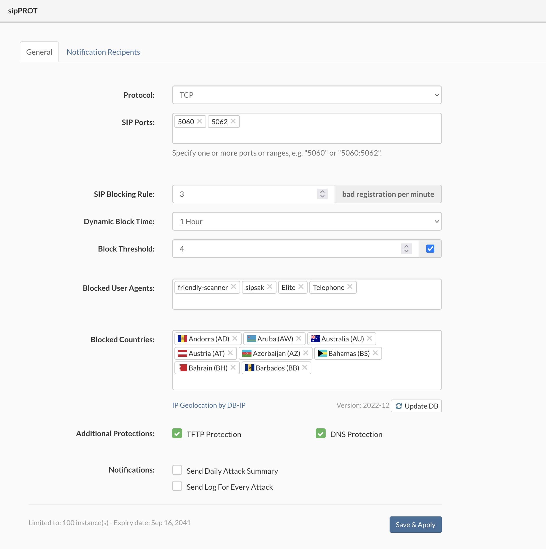
| Field | Description |
|---|---|
| Protocols: | Specify what protocols to watch for attacks TCP, UDP, or both. |
| SIP Ports: | Specify one or more ports or ranges, e.g., "5060" or "5060:5062". |
| SIP Blocking Rule: | Specify the maximum number of unauthorized registration attempts per minute before blocking the attacker's IP for the time selected. |
| Dynamic Block Time: | Select, for how long the IP addresses will remain blocked after successfully preventing the attack. |
| Block Threshold: | Block threshold defines how many times an IP will be dynamically blocked before it is permanently blocked by appending it to the deny list. The acceptable range is (1-20). |
| Blocked User Agents: | Specify the User-agent/scanner for sipPROT to match and block incoming traffic. The scanners parameter contains a comma-separated list of available SIP scanners (user agents) immediately stopped if detected. IMPORTANT: Try to hold the list of scanners as short as possible, given that it could affect overall system performance if the list is too long. |
| Blocked Countries: | Pick the countries to block incomming traffic from. sipPROT will block the whole range of addresses belonging to the selected countries. The list of countries automatically updates across the SERVERware hosts. There is also a button for manual updates of the GEO-IP database. |
| Additional Protections: | |
| TFTP option allows you to protect your server against TFTP brute force attacks, using rate limit. The default rate limit is 10/minute, allowing a maximum of 100 burst requests. | |
| DNS feature is vulnerability protection for older systems that might be affected by glibc stack-based buffer overflow in getaddrinfo() security flaw, otherwise named CVE-2015-7547. It is enabled by default. | |
| If you are unsure what the feature is for, you should not modify this option under no circumstances. | |
| Notifications: | |
| - Send Daily Attack Summary will send notifications to the selected recipients if checked. | |
| - Send Log For Every Attack will send notifications for every attack (Attention frequent logs).The default value is 1/ hour, meaning it will send a message every hour in case of some SIP attack. | |
| SERVERware/PBXware must have a working SMTP account set for notifications to work. | |
| Notification recipients | |
| To update Notification Recipients List, select Notification Recipients tab in General menu, select or search a user in the list and click on Add button. To remove Notification Recipient from the List, click on the Remove button in the same line. Confirmation dialog appears. Click Yes to remove Notification Recipient. | |
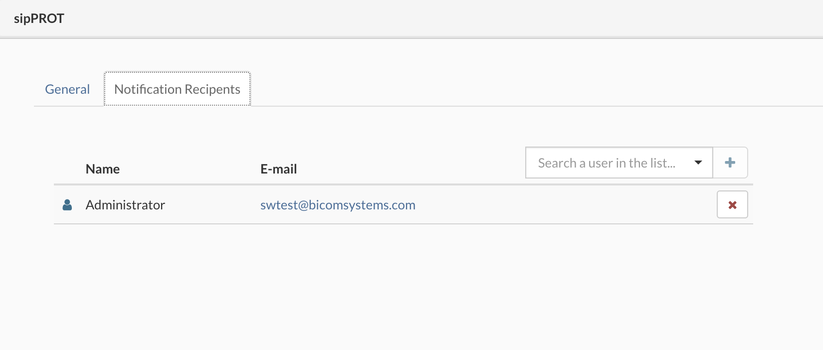 |
|
¶ Allow list
Allow list is the list of IP addresses allowed uninterrupted access to the system; this list is manually populated via form or CSV file upload.

To add an IP address to the lists, select the Allowlist IP Addresses tab, press the "+" button enter Network or IP Address, enter Note (not mandatory), and click the Add button.
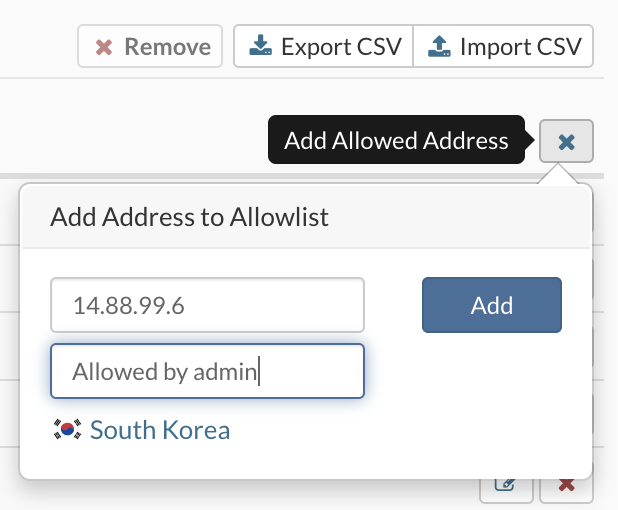
To add multiple IP addresses into Allowlist, there is an Import CSV option in the upper right corner. Select the CSV file with the list of IP addresses you wish to add to the Allowlist and click on the Upload button. There is also an option to export all Allowlist IP addresses to a CSV file.
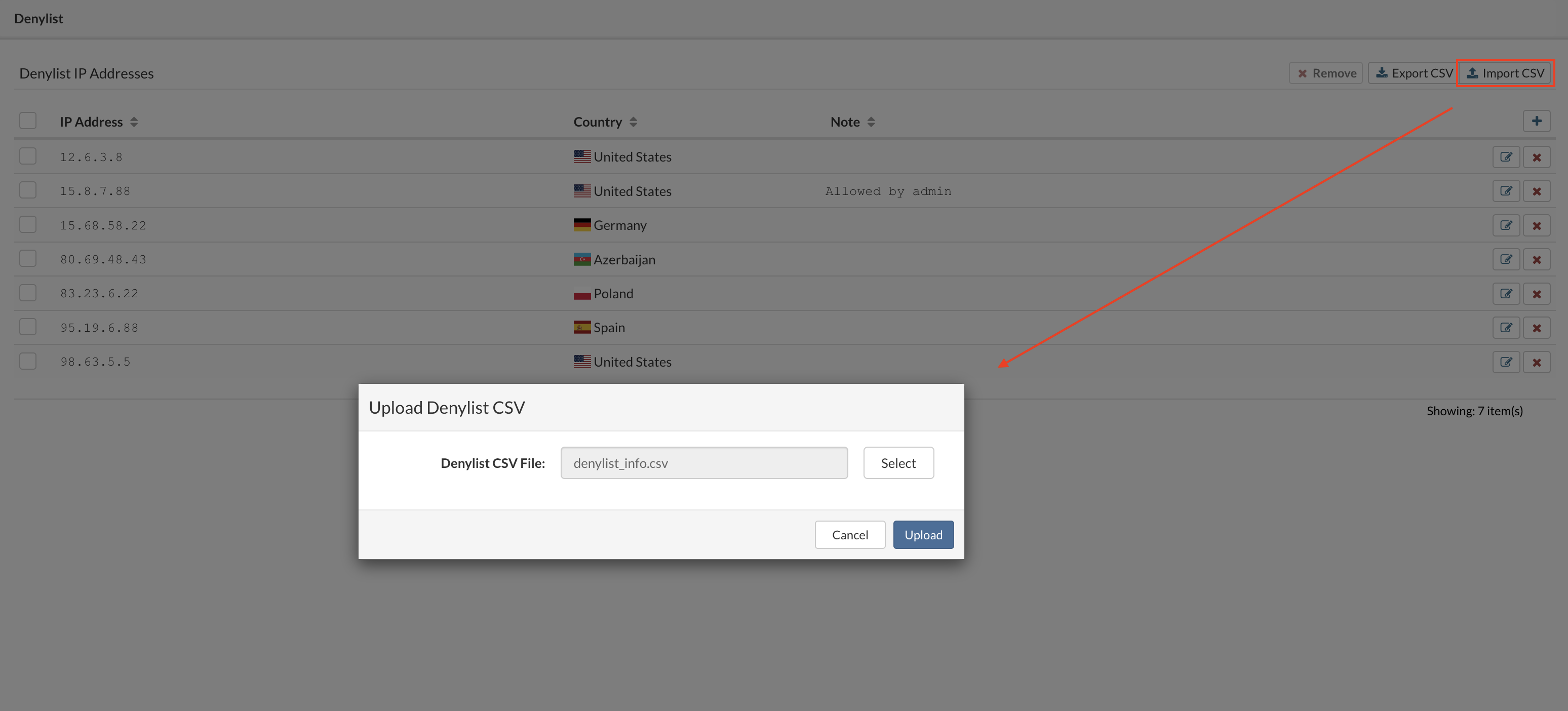
Removing a Network or IP Address from the List can be executed in two ways. First, there is an option to remove one or multiple IP addresses by selecting one or multiple IP addresses and then clicking on the Remove button. And there is another option to remove all IP addresses from the list by clicking on the select all checkbox and then clicking on the Remove button. A confirmation dialog appears. Click Yes to remove the Network or IP Address. Changes made to the Lists are applied automatically.
Download CSV templates ---> link to Template
The Allow list has a priority over other lists, e.g., if we add the same IP to deny list and allow list, the IP will be granted access to the system, and the deny list is ignored.
This is often a use case, when one is bloking network or range of IPs "192.168.50.0/24" and we want to allow only one IP from the range "192.168.50.15" to access the system.
¶ Deny list
Deny list is the list of IP addresses with the restricted access to the system; this list is manually populated via form or CSV file upload.

To add an IP address to the lists, select the Allowlist IP Addresses tab,press the "+" button enter Network or IP Address, enter Note (not mandatory), and click the Add button.

To add multiple IP addresses into Denylist, there is an Import CSV option in the upper right corner. Select the CSV file with the list of IP addresses you wish to add to the Denylist and click on the Upload button. There is also an option to export all Denylist IP addresses to a CSV file.

Removing a Network or IP Address from the List can be executed in two ways. First, there is an option to remove one or multiple IP addresses by selecting one or multiple IP addresses and then clicking on the Remove button. And there is another option to remove all IP addresses from the list by clicking on the select all checkbox and then clicking on the Remove button. A confirmation dialog appears. Click Yes to remove the Network or IP Address. Changes made to the Lists are applied automatically.
Download CSV templates ---> link to Template
¶ Dynamic deny list
sipPROT > Dynamic Denylist, from list of blocked dresses in this menu one can unblock IP address manually or wait for timeout and block will be removed automatically.
For easier management of the sipPROT-blocked IPs and inspection/debugging, the sipPROT dynamic deny list displays the exact user agent (scanner) and country of origin for every successfully stopped attack.

¶ Working with sipPROT CLI
The new updated version of sipPROT comes with updated CLI commands and outputs. CLI autocomplete is added for the sipPROT commands.
# sipprot --help
# Usage:
     sipprot [status|report|version|check]
# status:
         prints number of IPs per list
     --all  prints allow, deny, and dynamic deny lists
     --allow prints allow list
     --deny  prints deny list
     --dynamic prints dynamic deny list
# report:
     prints out daily attack report
# version:
     prints out sipPROT version
# check:
     checks if the provided IP is in any of the following: allowlist, denylist, dynamic denylist
     example: sipprot check 192.168.0.1
/etc/init.d/sipprotd [start|stop|status]
To mannualy start the sipPROT use the following command:
- /etc/init.d/sipprotd start
sipPROT will automatically be started on system restart. After sipPROT is started the configuration variable will be loaded from the configuration file. This is the location of the configuration file:
- /home/sipprot.conf
During the startup sipPROT will also read IP addresses from the Allow and Deny lists. IP addresses listed in the deny list will be permanently blocked and IP addresses listed in the white list will be permanently allowed.
To add an IP address to the deny list you have to add the IP address in file
/home/sipprot.denylist
Only one IP address per line is allowed. Lines that which starts with character # will be ignored. Here is an example of a black list file:
# One IP Address per line
192.168.1.1
192.168.1.2
In the above example, IP addresses 192.168.1.1 and 192.168.1.2 are in the deny list and those IP will be permanently blocked.
To add an IP address to the white list you have to add the IP address in file
/home/ sipprot.allowlist
Only one IP address per line is allowed. Lines which starts with character # will be ignored. Here is an example of a allow list file:
# One IP Address per line
192.168.2.1
192.168.2.2
In this example IP addresses 192.168.2.1 and 192.168.2.2 will not be blocked by sipPROT.
To stop sipPROT manually run following command:
- /etc/init.d/sipprotd stop
This command will stop sipPROT module and disable firewall rules created by sipPROT.
To get information about sipprot status use the following command:
- sipprot status
This command will give the following information:
> ~# sipprot status
> +---------------------+------------+
> |        LIST         | NUM OF IPS |
> +---------------------+------------+
> | Allow               |          0 |
> +---------------------+------------+
> | Deny                |          0 |
> +---------------------+------------+
> | Dynamic (permanent) |          0 |
> +---------------------+------------+
> | Dynamic (temporary) |          0 |
> +---------------------+------------+
The list of IPs dynamically blocked by sipPROT is a list of IPs that are blocked in the moment you execute the sipPROT status command.
These IPs will be blocked if the period between two attacks from that IP is less than the time defined by BLOCKTIME. BLOCKTIME is a variable defined in the configuration file "/home/sipprot.conf". For example, if BLOCKTIME is 600 seconds, the dynamically blocked IP will be blocked for the next 600 seconds. If there is no new attack from that IP after 600 seconds, sipPROT will unblock that IP. So for the IP to be blocked, there must be an occurrence of an attack during BLOCKTIME.
If an IP address is in the "List of IPs in the allow list," that IP will not be blocked by sipPROT.
If an IP address is in the "List of IPs blocked by the deny list," IP will be blocked regardless of whether an attack is coming from that IP.
¶ Settings
Settings menu expands into Storage, Archive and Networking.
¶ Storage
Storage view provides detailed information about storage hosts. Information provided is iSCSI IP Address and Storage Pools.
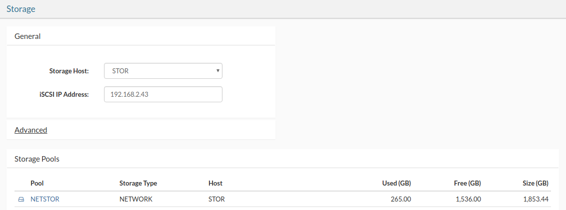
Advanced section allows you to enable/disable Failover to Storage, Processing on Storage options as well as set the Failover Timeout.
Failover To Storage allow the virtual servers to fall over to the storage in case that there are not enough processing hosts.
Processing on Storage enables VPS creation on storage hosts. Running VPSs on storage hosts is not recommended but if needed, this additional option is available on Cluster Edition.
Syslog on Storage Allow the storage server to run a centralized Syslog service and collect log messages from other hosts in the cluster.
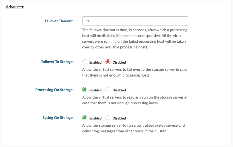
¶ Networking
Networking view allows you to add, configure and remove SERVERware network logical subnets.

¶ Adding logical subnet
To add a logical subnet, do the following:
In the Settings menu, select Networking view and click Add.
Add Subnet dialog appears. Select Type, enter Name and relevant network information. Check Use this subnet for VPS networking and provide bridge interface name if you need to use this subnet for VPS networking. Use netsetup to preconfigure bridge interface with the same name on all hosts in SERVERware cluster.
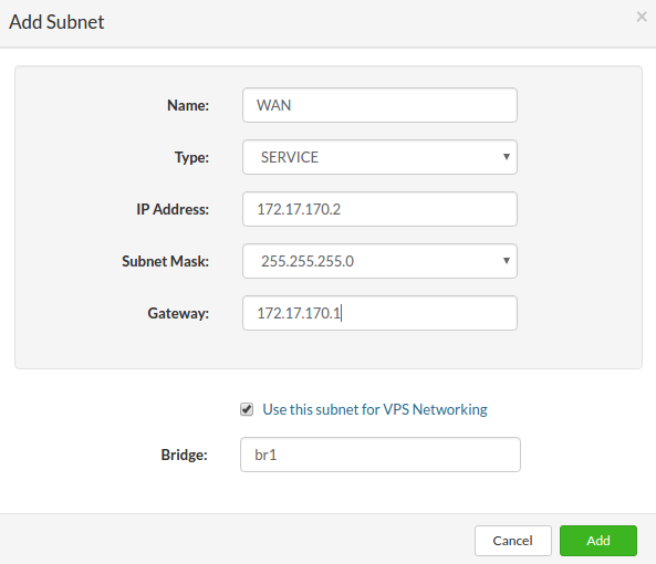
Click Add to add logical subnet.
¶ Removing logical subnet
Follow this procedure to remove a logical subnet:
¶ Extending IP address pool
To configure existing logical subnet, do the following:
In the Settings menu, select Networking view, logical subnet you need to configure and click Configure. Configure Subnet dialog appears.
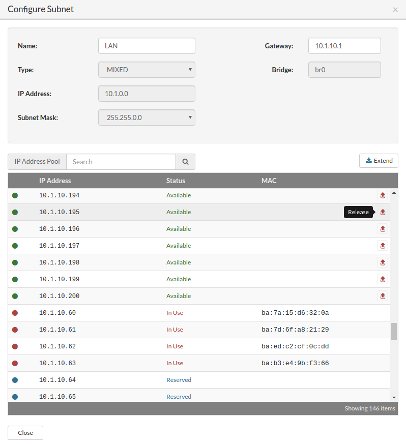
To extend IP Pool, click on Extend button. Extend IP Address Pool dialog appears.
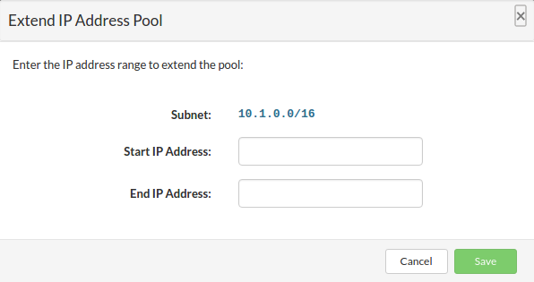
Enter the IP address range to extend the pool and click Save to extend IP address pool.
When done, click Close to exit Configure Subnet dialog.
¶ Removing IP address from the pool
In the Settings menu, select Networking view, logical subnet you need to configure and click Configure. Configure Subnet dialog appears.
To remove an IP address from the pool, click on Release button next to IP address in the list. Confirmation dialog appears.
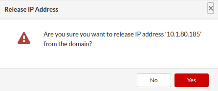
Click Yes to release IP address.
When done, click Close to exit Configure Subnet dialog.
¶ Create virtual network interface IPV4
Virtual networking enables communication between multiple machines (VPS). While physical networking connects computers through cabling and other hardware, virtual networking extends these capabilities by using software management to connect computers and servers over the Internet. It uses virtualized versions of traditional network tools, like switches and network adapters, allowing for more efficient routing and easier network configuration changes.
Virtual networking enables devices across many locations to function with the same capabilities as a traditional physical network.
This allows network administrators new and more efficient options to easily create a network connection between VPSs and greater flexibility in provisioning the network to specific needs and applications.
Capacity to move workloads across the network infrastructure without compromising service, security, and availability.
To create a new virtual IPV4 interface we need to first add a new virtual network.
In the main menu go to the Settings > Networking
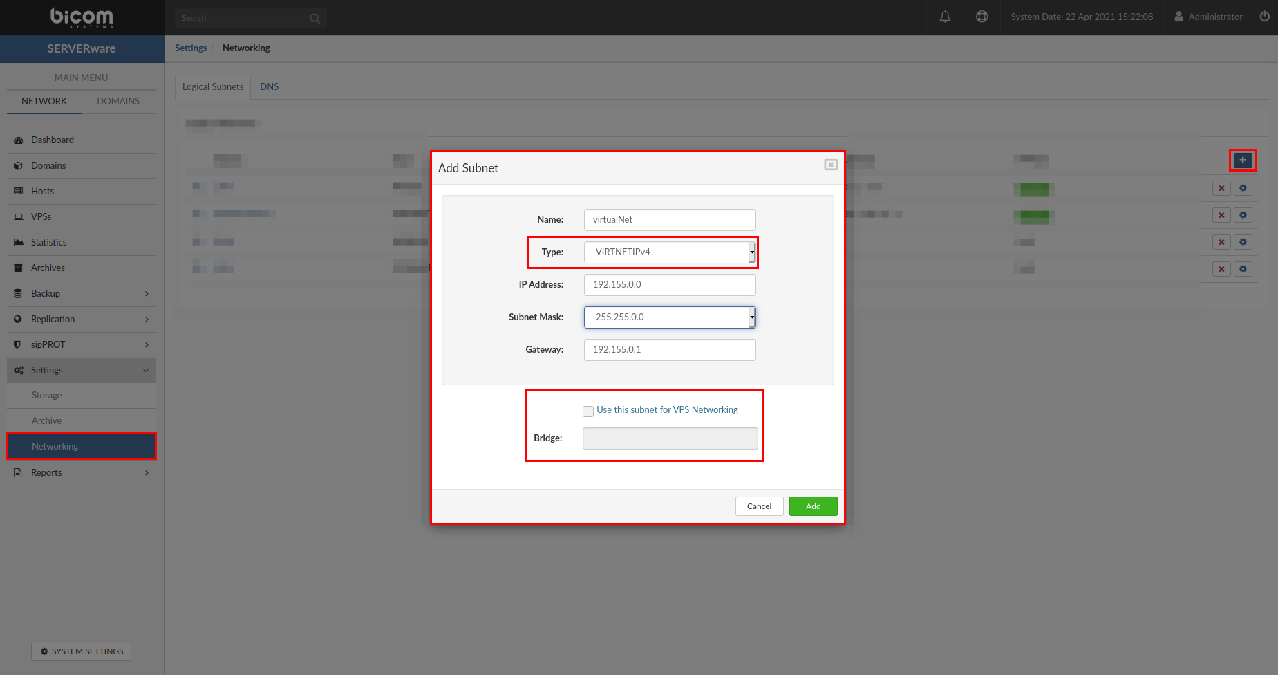
In the upper right corner select the "+" button, the popup will appear with the parameters for the network interfaces.
Enter the values required as follows:
NOTE: The Bridge option will be added automatically by the server and options in GUI will be grayed out.
When all fields are populated press the "Add" button to finish creating the new virtual network.
Now we need to add some IP addresses to the IP pool in the network we have just created, to do this press the little gear icon next to the network we have just created.

Then select press "initialize | Extend " and enter the range of addresses you want to add to the new virtual network
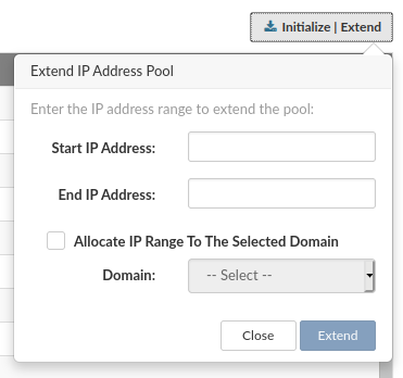
Optionally you can automatically allocate the range to the selected Partition.
Now we need to Edit/Create VPS and in the "network tab" for the selected VPS add the new virtual interface and select the address from the pool.
¶ Create virtual network interface IPV6
To create a new virtual IPV6 interface we need to first add a new virtual network.
In the main menu go to the Settings > Networking
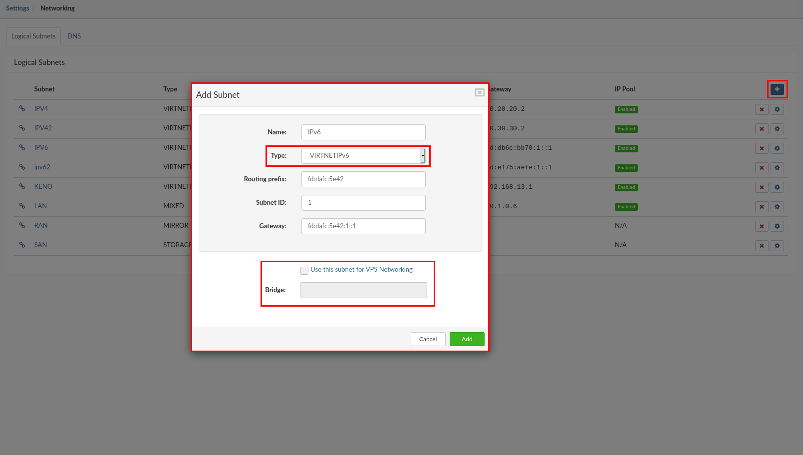
In the upper right corner select the "+" button, the popup will appear with the parameters for the network interfaces.
Enter the values required as follows:
NOTE: The Bridge option will be added automatically by the server and options in GUI will be grayed out.
When all fields are populated press the "Add" button to finish creating the new virtual network.
IPv6 addresses will be generated automatically when adding the interface to the VPS so there is no option to add the IP pool in the IPV6 interface.
Now we need to Edit/Create VPS and in the "network tab" for the selected VPS add the new virtual interface and select the address from the pool.
¶ DNS Zones
DNS plugin will allow using SERVERware controller as authoritative partition name server and it will be able to resolve address of each VPS based on SERVERware database.
For example, SERVERware might be assigned with domain zone cluster1.mydomain.com, and it will be able to resolve IP addresses for each host and VPS it is responsible for, based on VPS name given e.g. pbx1.cluster1.mydomain.com.
Depending on the client source address this plugin will resolve IP addresses of the VPS from matching private or public networks.
Immediate benefits:
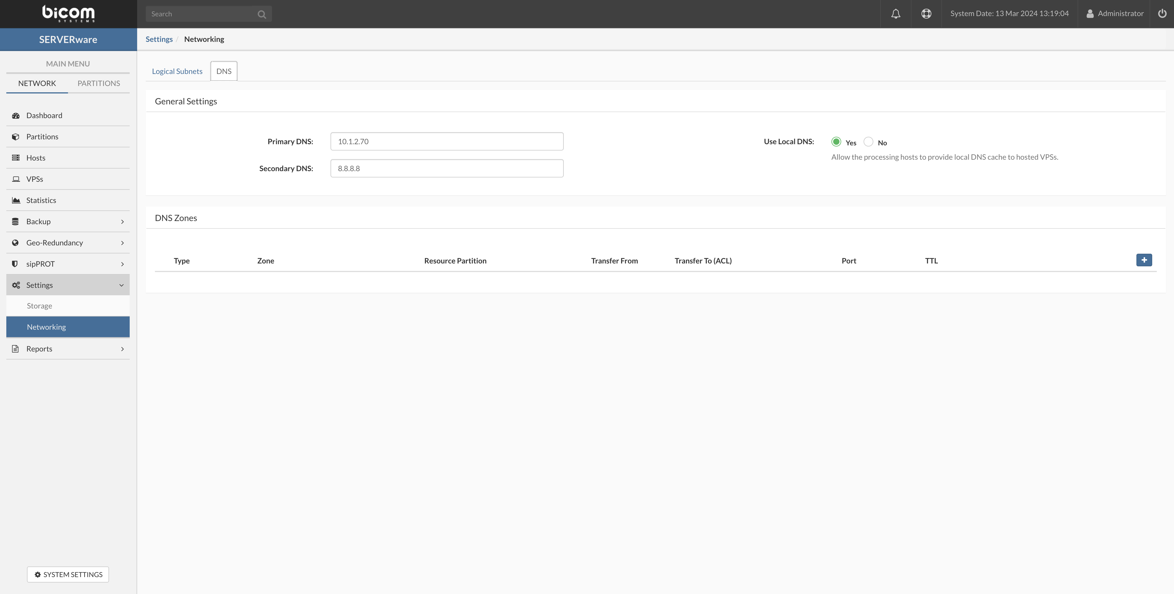
To configure the DNS zone go to the Networking > DNS tab
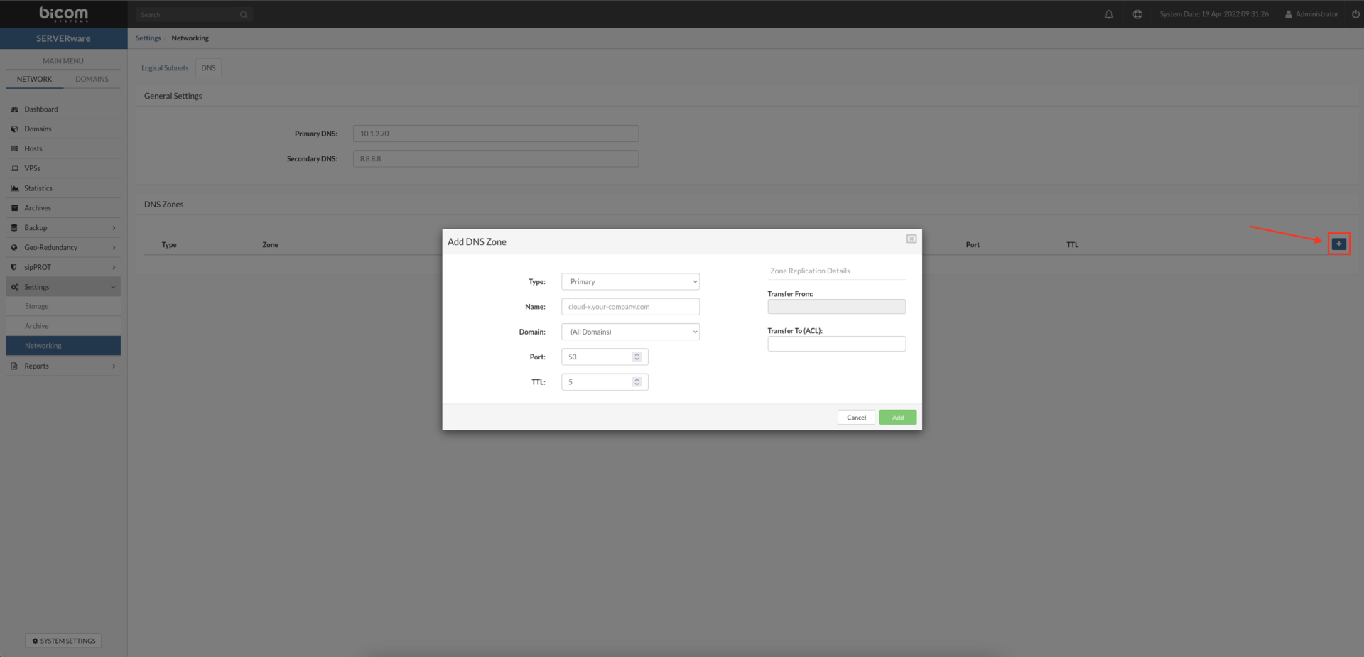
Default DNS on all VPSs will be always set to CONTROLLER IP
To test our newly added DNS zone we can use the dig command from the CLI to resolve the IP address from the VPS.
~$ dig @< IP of SERVERware CONTROLLER > < name of the VPS >.mydomain.xyz
Example:
~$ dig @10.1.35.63 PBXware60.mydomain.xyz
 ; <<>> DiG 9.11.3-1ubuntu1.14-Ubuntu <<>> @10.1.35.63 PBXware60.mydomain.xyz
 ; (1 server found)
 ;; global options: +cmd
 ;; Got answer:
 ;; ->>HEADER<<- opcode: QUERY, status: NOERROR, id: 16840
 ;; flags: qr aa rd; QUERY: 1, ANSWER: 1, AUTHORITY: 0, ADDITIONAL: 1
 ;; WARNING: recursion requested but not available

 ;; OPT PSEUDOSECTION:
 ; EDNS: version: 0, flags:; udp: 4096
 ; COOKIE: 8962e1899e70b4bb (echoed)
 ;; QUESTION SECTION:
 ;PBXware60.mydomain.xyz.		IN	A

 ;; ANSWER SECTION:
 pbxware60.mydomain.xyz.	5	IN	A	10.1.35.70

 ;; Query time: 36 msec
 ;; SERVER: 10.1.35.63#53(10.1.35.63)
 ;; WHEN: Mon Apr 19 10:16:42 CEST 2021
 ;; MSG SIZE  rcvd: 101
Example with the host:
~$ dig @<IP of SERVERware CONTROLLER> <Name of the processing/storage Host>.mydomain.xyz
  ~$ dig @10.1.35.63 PROC1.mydomain.xyz

 ; <<>> DiG 9.11.3-1ubuntu1.14-Ubuntu <<>> @10.1.35.63 PROC1.mydomain.xyz
 ; (1 server found)
 ;; global options: +cmd
 ;; Got answer:
 ;; ->>HEADER<<- opcode: QUERY, status: NOERROR, id: 32100
 ;; flags: qr aa rd; QUERY: 1, ANSWER: 2, AUTHORITY: 0, ADDITIONAL: 1
 ;; WARNING: recursion requested but not available

 ;; OPT PSEUDOSECTION:
 ; EDNS: version: 0, flags:; udp: 4096
 ; COOKIE: 2a583c3da04e3299 (echoed)
 ;; QUESTION SECTION:
 ;PROC1.mydomain.xyz.		IN	A

 ;; ANSWER SECTION:
 proc1.mydomain.xyz.	5	IN	A	10.1.35.14  <--- The host LAN IP is resolved
 proc1.mydomain.xyz.	5	IN	A	192.168.4.14  <---- The host SAN IP is also resolved

 ;; Query time: 2 msec
 ;; SERVER: 10.1.35.63#53(10.1.35.63)
 ;; WHEN: Mon Apr 19 11:11:27 CEST 2021
 ;; MSG SIZE  rcvd: 127
¶ Reports
Reports menu expands into System Logs, Alarm logs and User Sessions.
¶ System Logs
All events that occur in SERVERware are recorded in System Logs. Apart from general information and system management, System Logs can also be used for debugging and analysis, also there is available filter for the displaying logs.
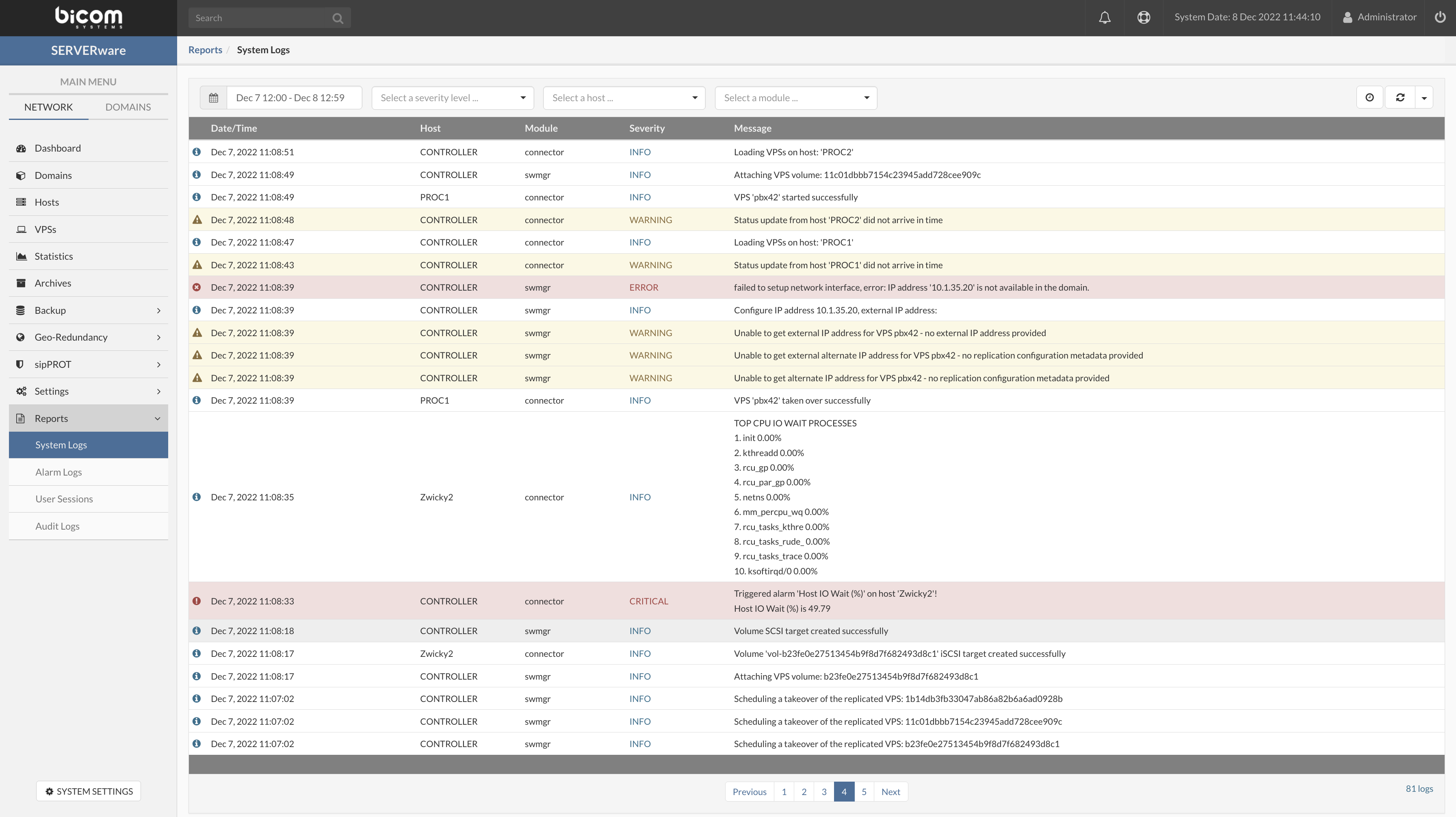
¶ Alarm logs
All triggered alarms are recorded to alarm log, can also be used for debugging and analysis, also there is available filter for the displaying logs.
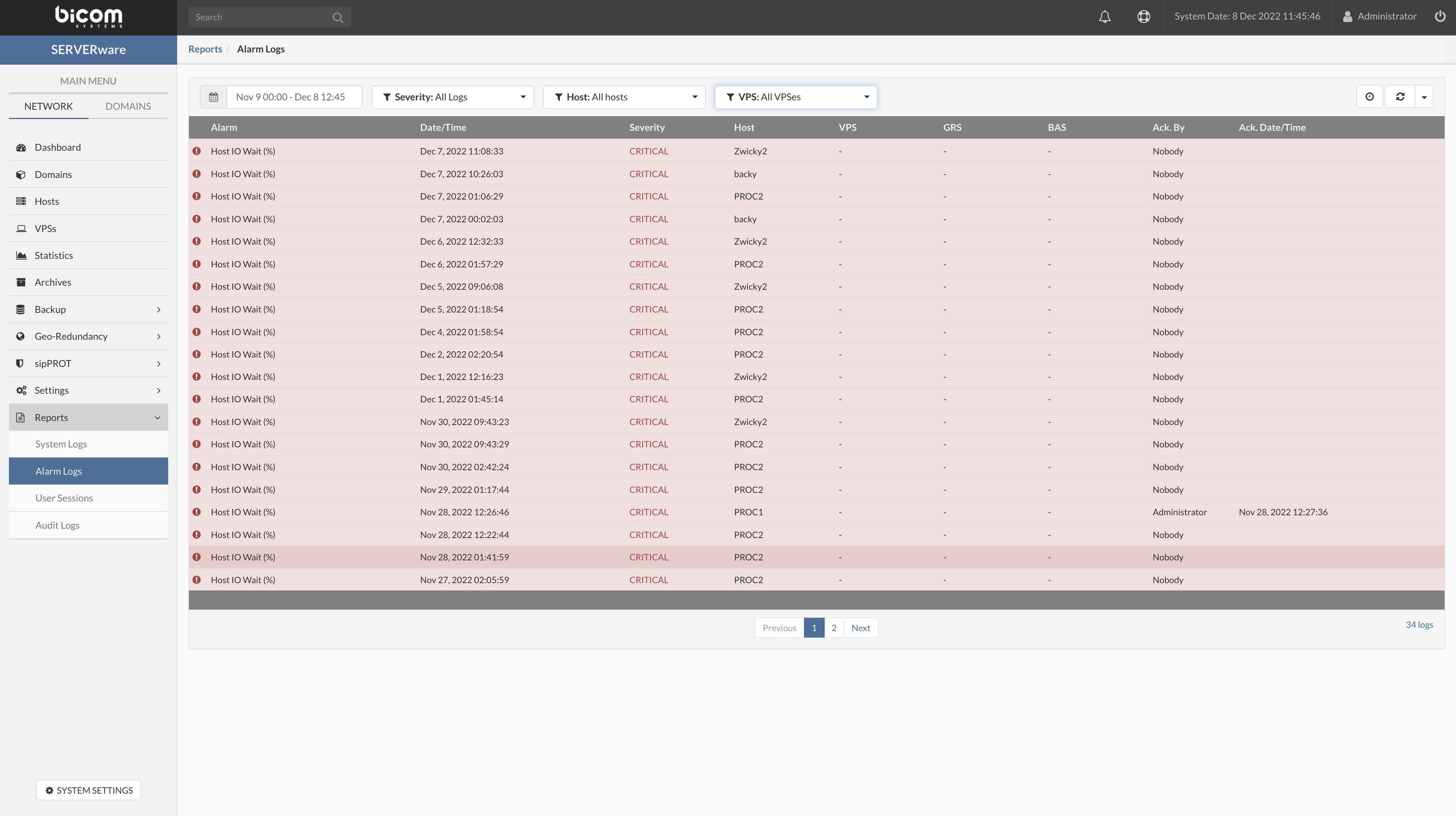
¶ User Sessions
User Sessions view provides information on current connections to the SERVERware GUI as well as connection history and activity. The following information is provided: user, start/end time of connection, IP address and user agent.
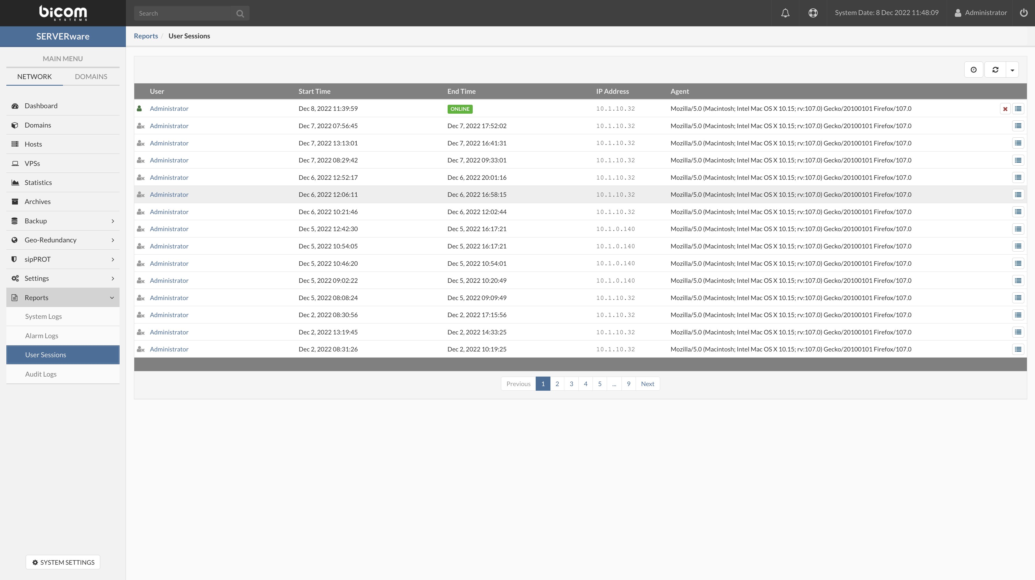
¶ Audit Logs
Audit logs are a record of actions that have been performed within a SERVERware. These logs typically include information about who performed the action, when the action was performed, and what the action was. Audit logs can be used to track changes made to a SERVERware, as well as to detect and investigate potential security incidents. In many cases, audit logs are considered an important tool for maintaining the security and integrity of a system, as they can provide valuable information for auditors and SERVERware administrators.
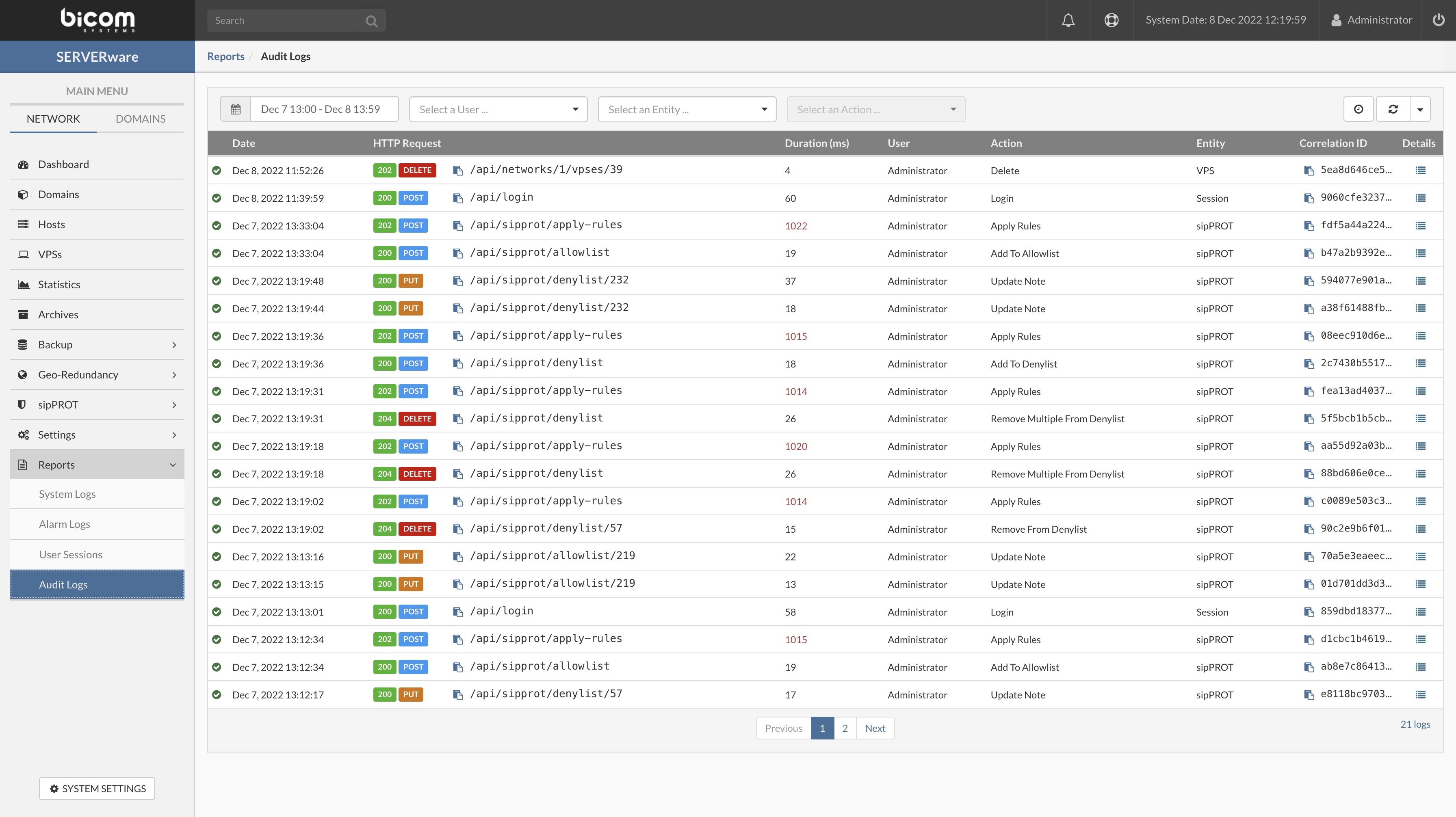
The filter is implemented so it can help SERVERware administrators to easier search and analyse Audit logs. By clicking on Details popup will appear with additional details about the action.
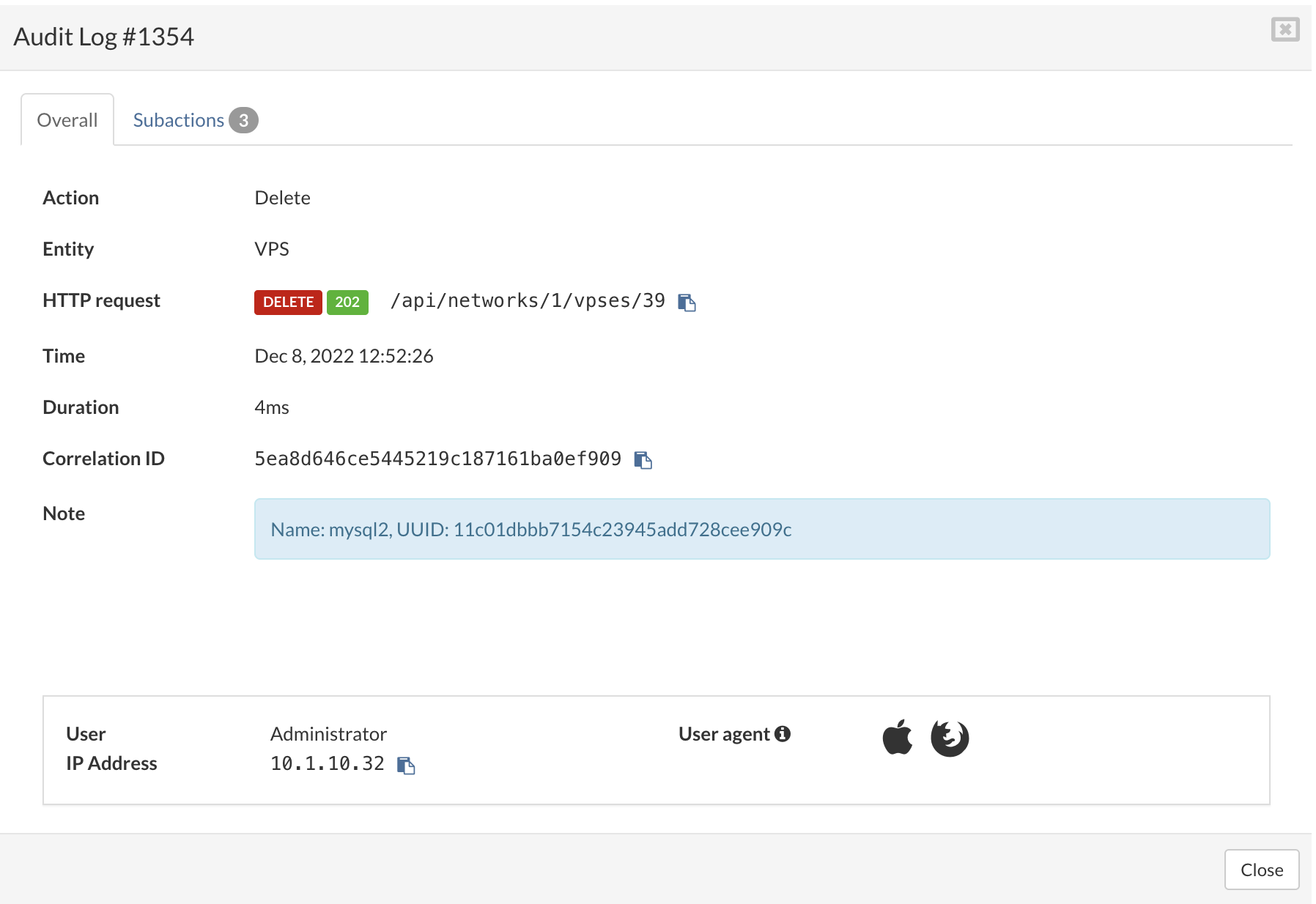
All sub-actions are previewed on the Subaction tab.
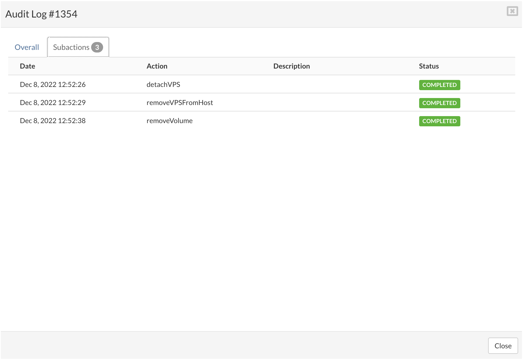
¶ System Settings
System Settings mode allows you to manage various system settings in SERVERware.
To enter/exit System Settings mode, click on the button System Settings.

¶ Administrators
Administrators menu allows creation, editing and removal of SERVERware GUI Administrators.
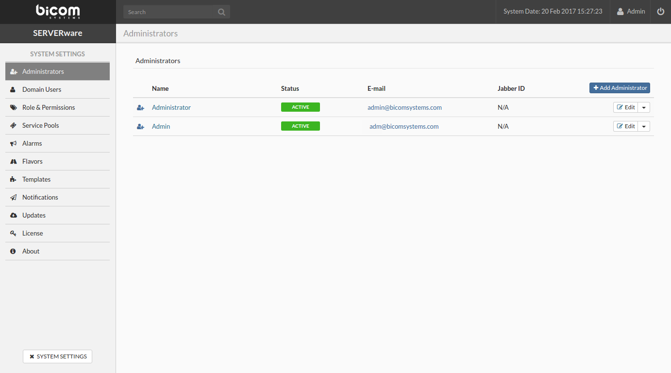
¶ Adding administrator account
Follow this procedure to add administrator account:
In the Administrators view, click Add.
Add User dialog appears. Select User Role, Status and enter personal user information.
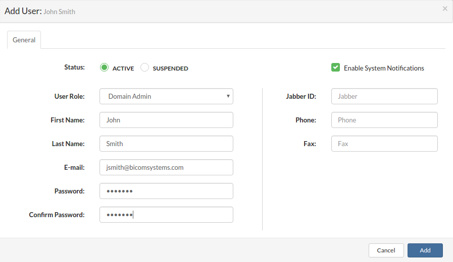
Click Add to add administrator.
¶ Removing administrator account
Follow this procedure to remove the administrator account:
¶ Demoting administrator account to user account
Follow this procedure to demote an administrator account to a user account:
¶ Partition Users
Partition Users menu allows creation, editing and removal of SERVERware GUI users as well as assignment of various roles and permissions.
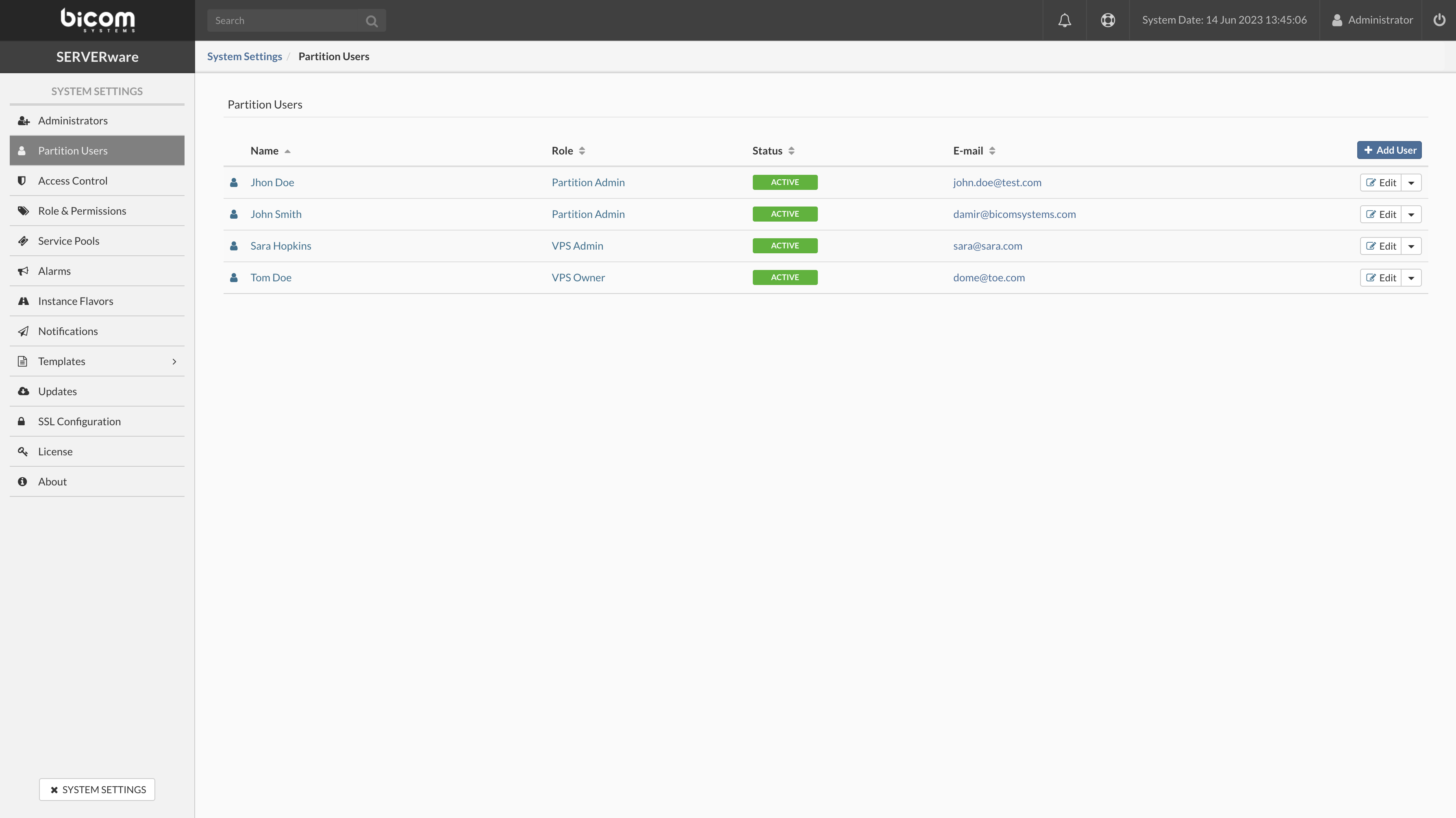
¶ Adding user account
Follow this procedure to add a user account:
In the Partition Users view, click Add User.
Add User dialog appears. Select User Role, Status and enter personal user information.

Click Add to add user.
¶ Removing user account
Follow this procedure to remove a user account:
¶ Promoting user account to administrator account
Follow this procedure to promote a user account to an administrator account:
¶ Access Control
Access control is the access management feature for SERVERware Administration.
In this menu, we have options for managing Blocked IP, Allowed IP, and configuration of the automatic lockout after failed login attempts.
Login Lockout
Configure the limit for the allowed failed login attempts. User IP will be blocked after the specified number of failed attempts within the specified retry time period in minutes.
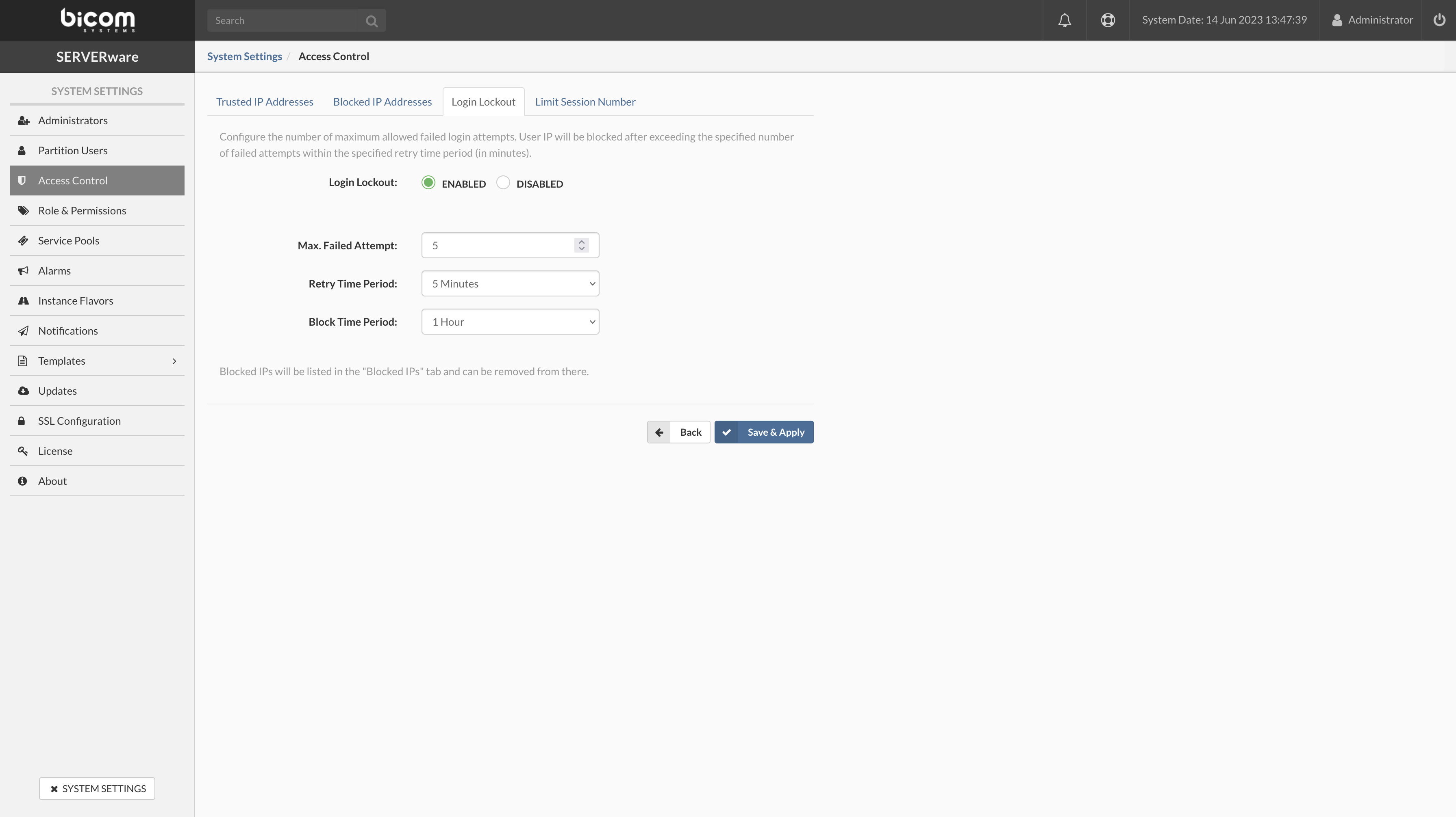
If all of the rules above are met the user account will be blocked after "n" failed attempts in "n" minutes, and will be added to the "Blocked IP Addresses" list.
Blocked IP Addresses
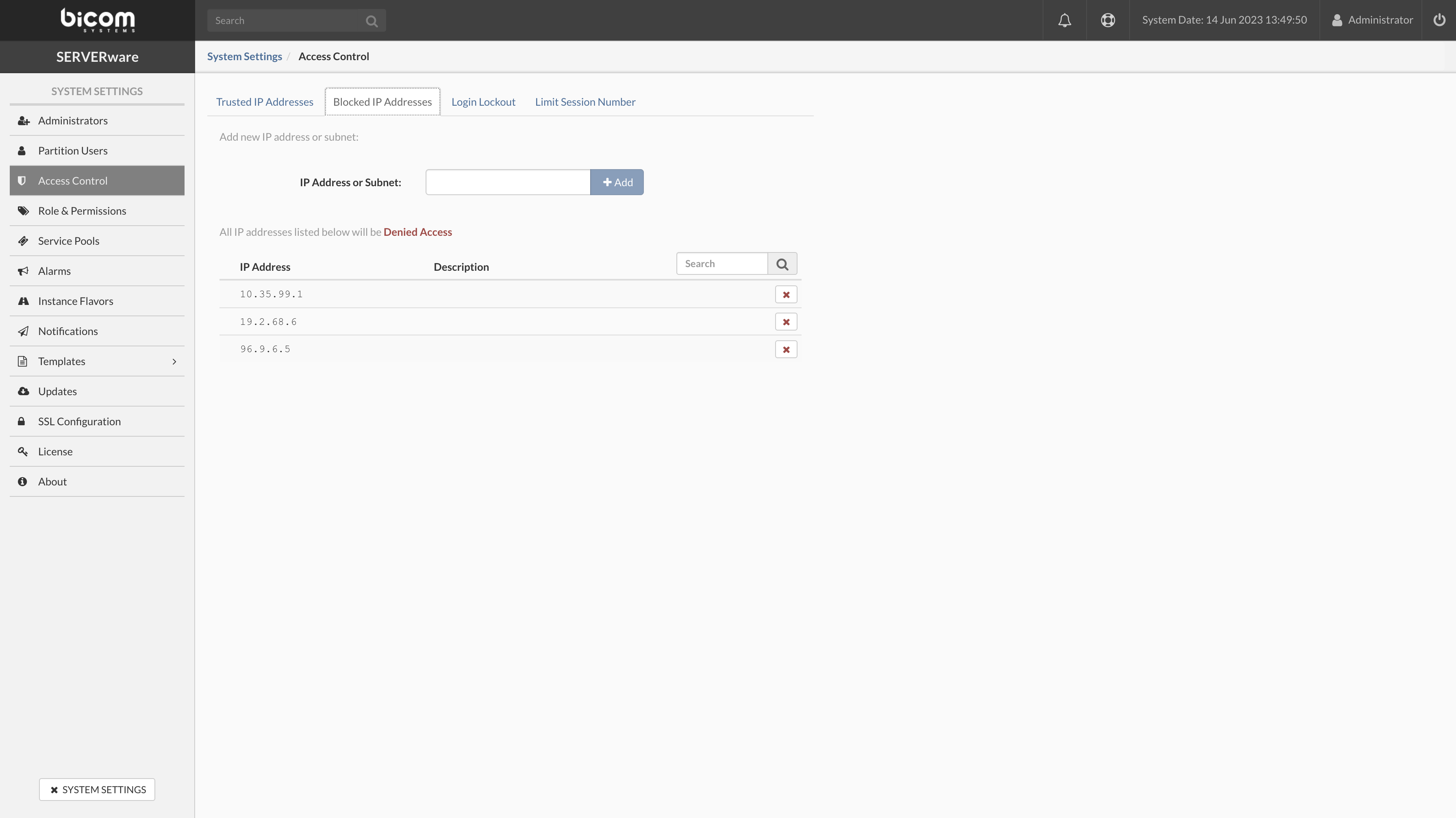
¶ Trusted IP Addresses
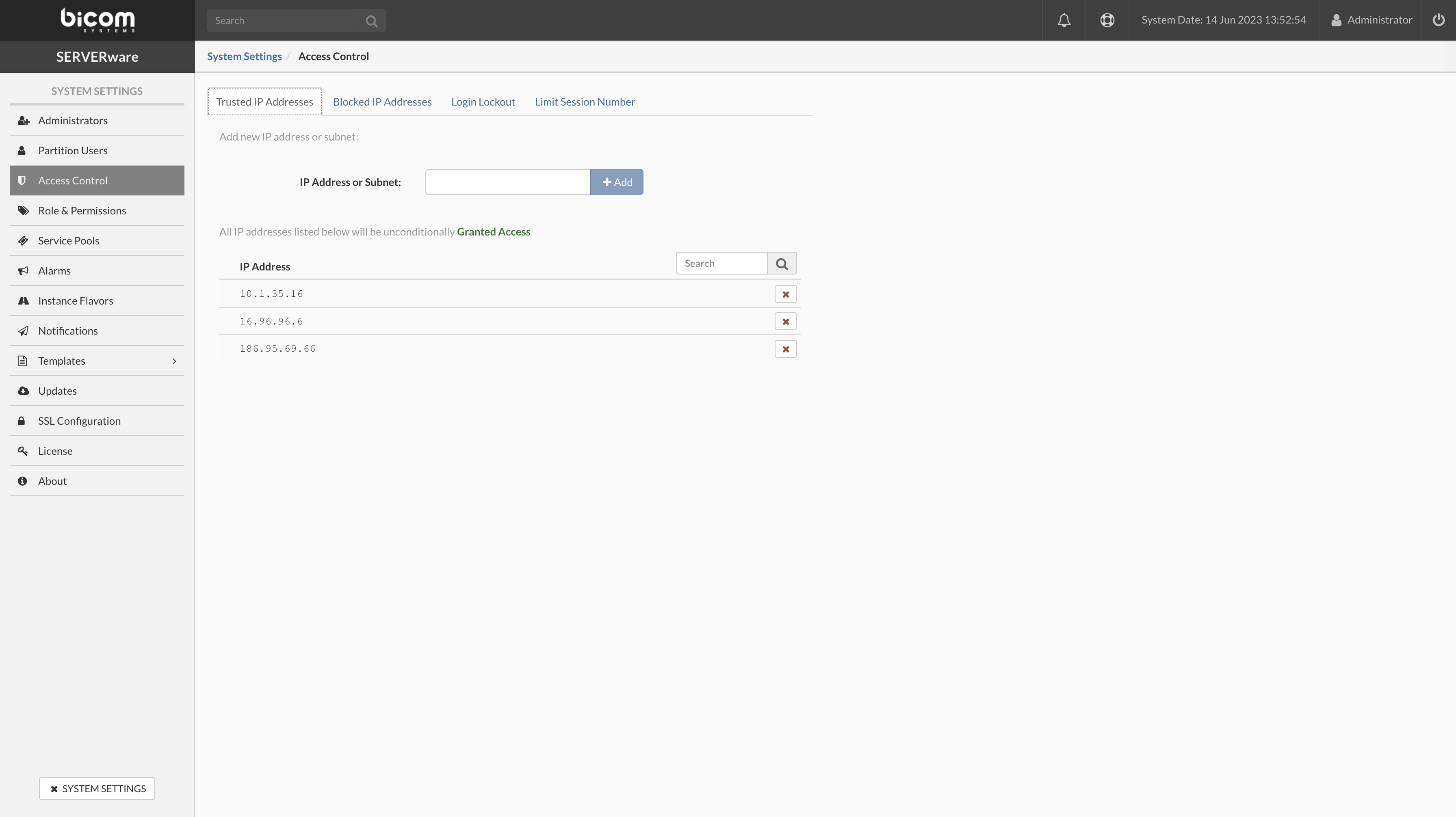
¶ Limit Session Number
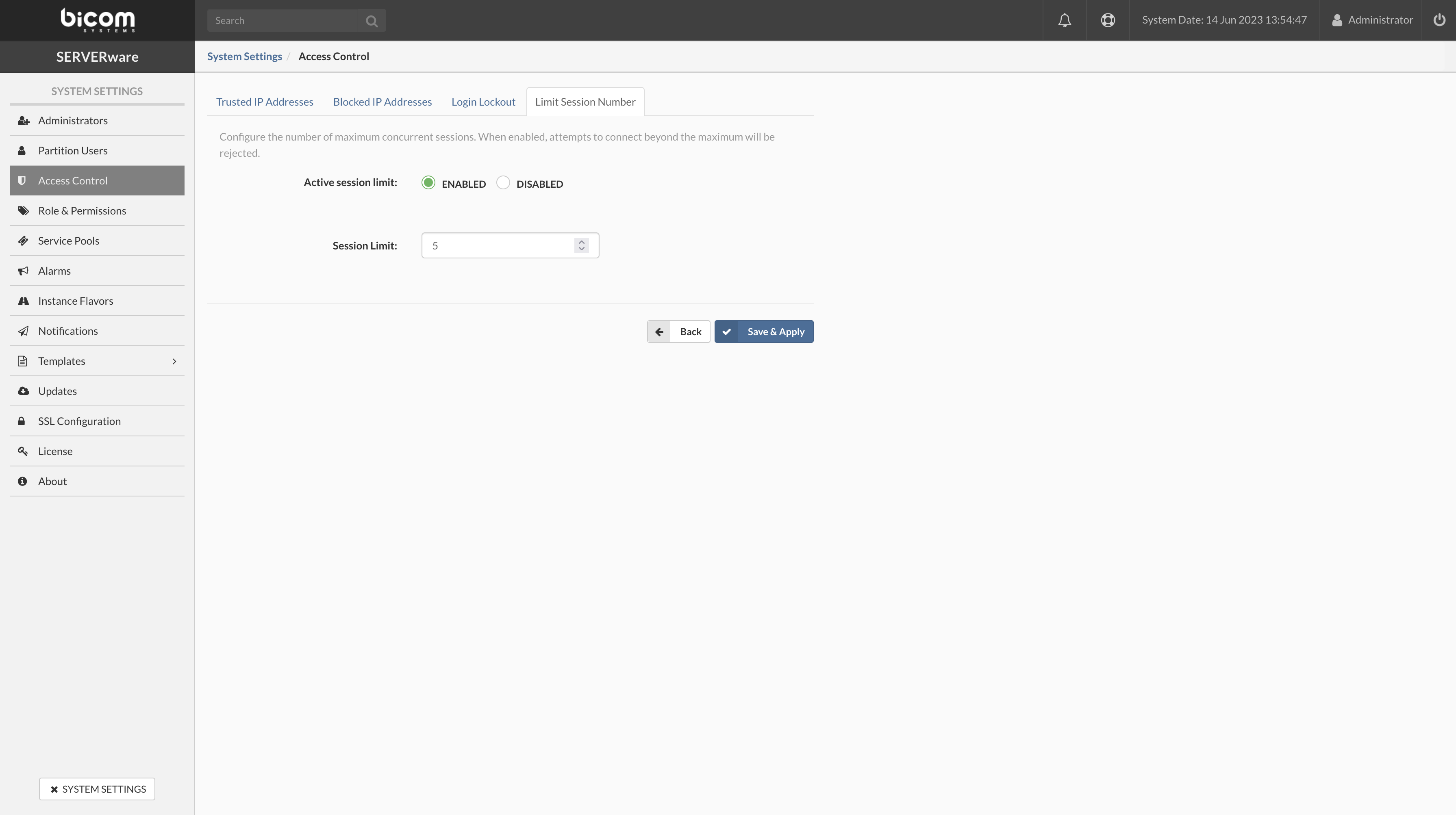

¶ Role & Permissions
Use Role & Permissions view to add, edit or remove roles and permissions that can be assign to the SERVERware GUI users.
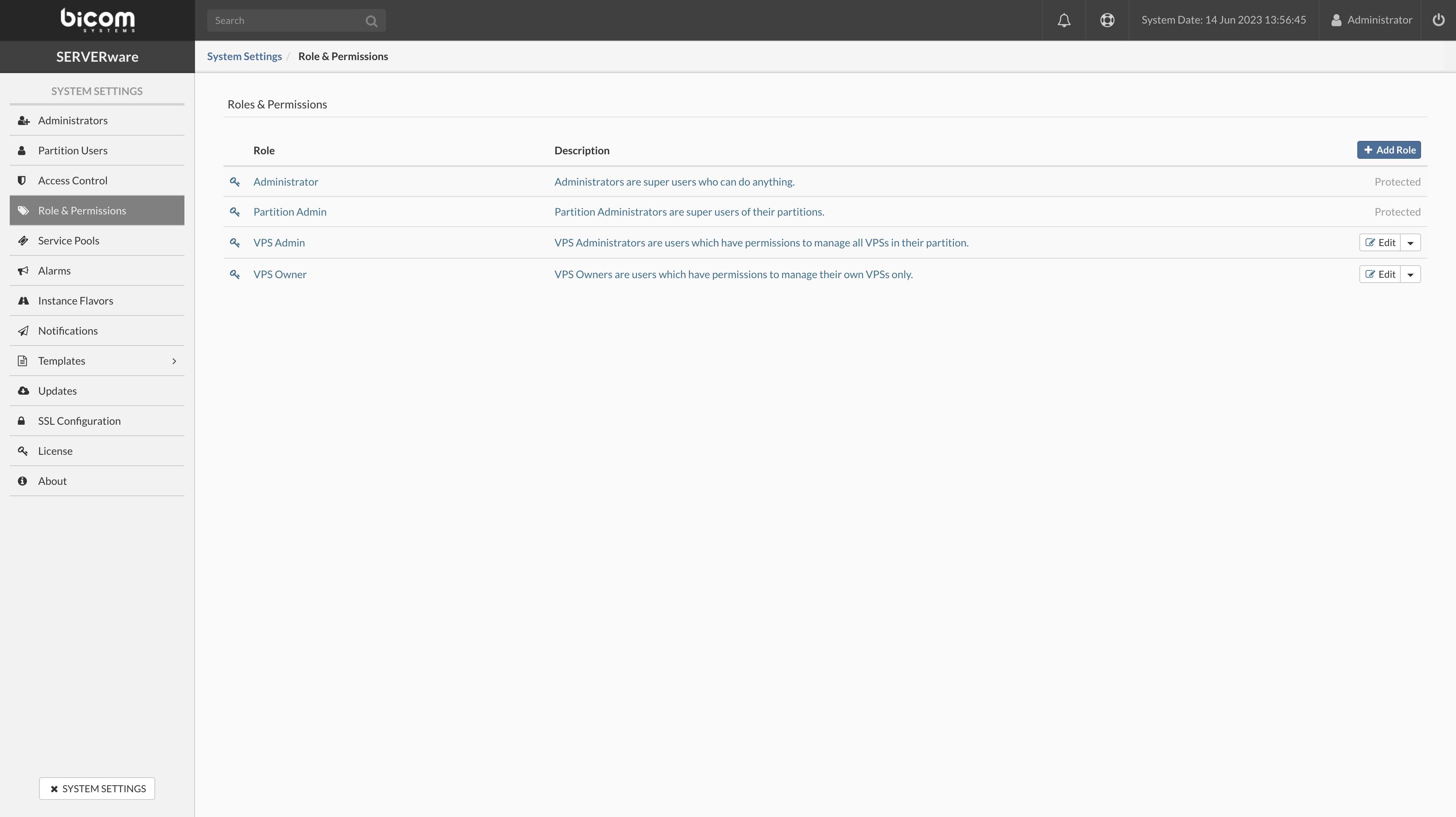
¶ Adding role
To add a role, do the following:
In the Role & Permissions view and click Add Role.
Add Role dialog appears. Enter name, description and set permissions.
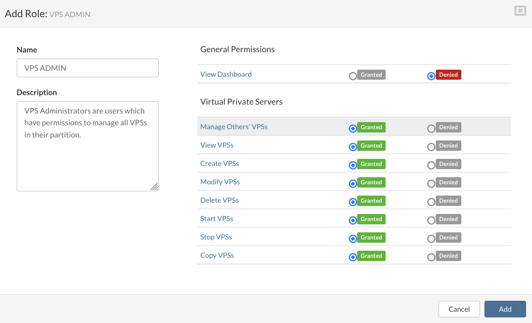
Click Add to add role.
¶ Removing role
Follow this procedure to remove a role:
¶ Service Pools
Service Pools tab allows you to add and remove service pools.

¶ Adding service pool
To add a new service pool, do the following:
In the Service Pools view and click Add Service Pool.
Enter Name, select Service Type and click Save.

¶ Removing service pool
Follow this procedure to remove a service pool:
¶ Alarms
Alarms view is used for setup and configuration of various SERVERware alarms. Alarms can be configured to send notifications when specific conditions are met.
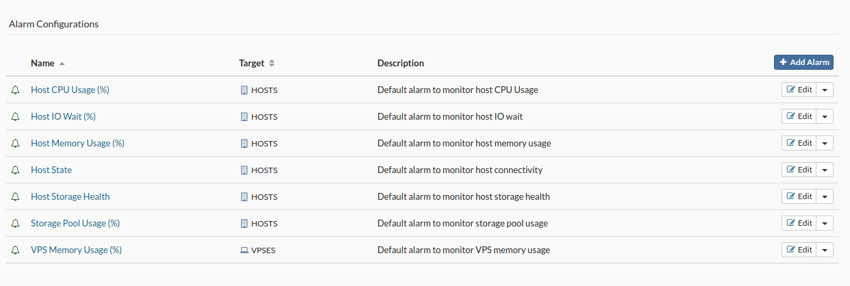
¶ Adding alarm
To add an alarm, do the following:
In the Alarms view, click Add Alarm. Configure New Alarm dialog appears.
Select alarm state, monitoring target, enter name, description and click next.
In the Triggers tab, select trigger, operator, enter warning and critical conditions, click Save Trigger and then click next.
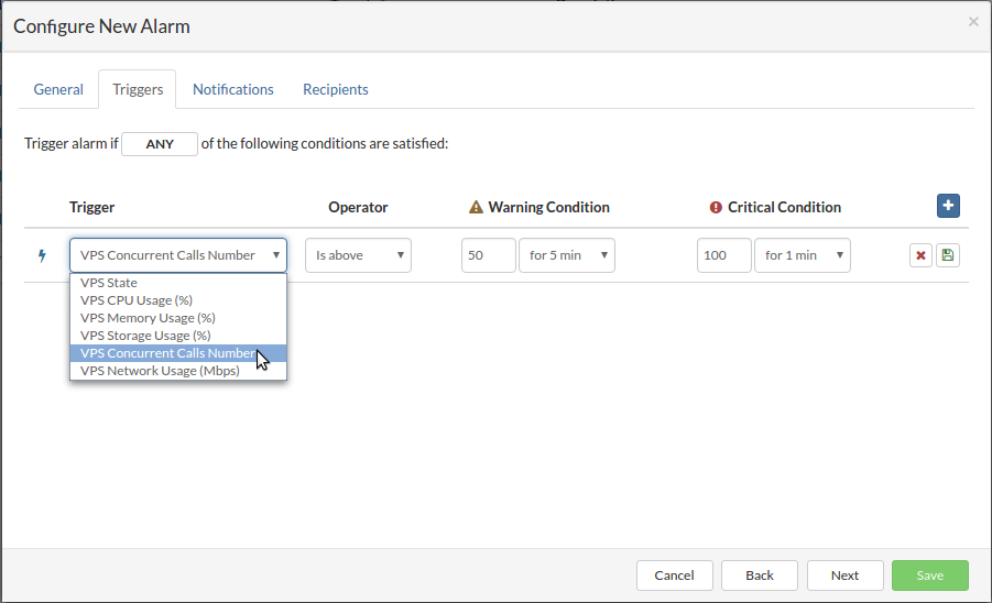
In the Notifications tab, configure notifications for individual alarm state changes by selecting Notify and by checking on delivery methods. When all notifications are configured, click next.
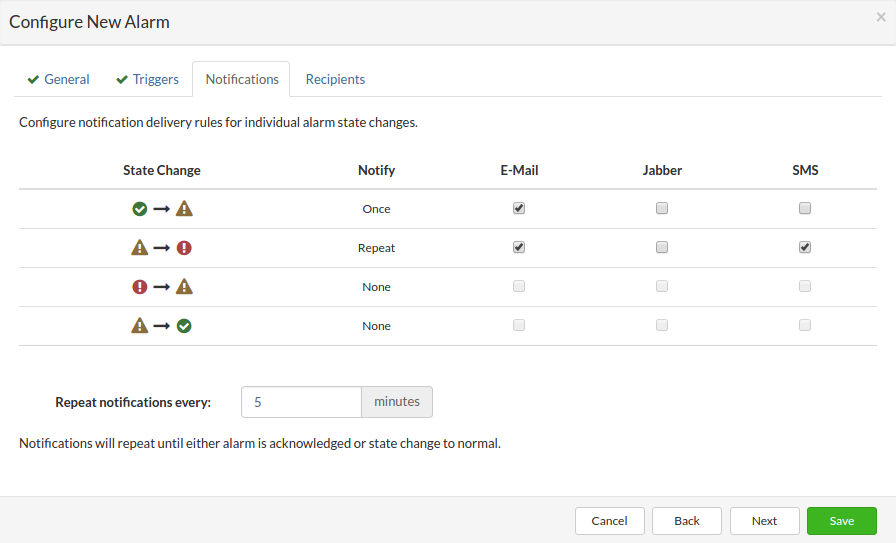
In the Recipients tab, select groups that will receive notifications and click Save to add new alarm.
¶ Removing alarm
Follow this procedure to remove an alarm:
¶ Flavors
Under the Flavors menu, it is possible to add, edit and remove Virtual Server Flavors. Flavors represent preconfigured set of hardware resources that can be assigned to a VPS upon creation.
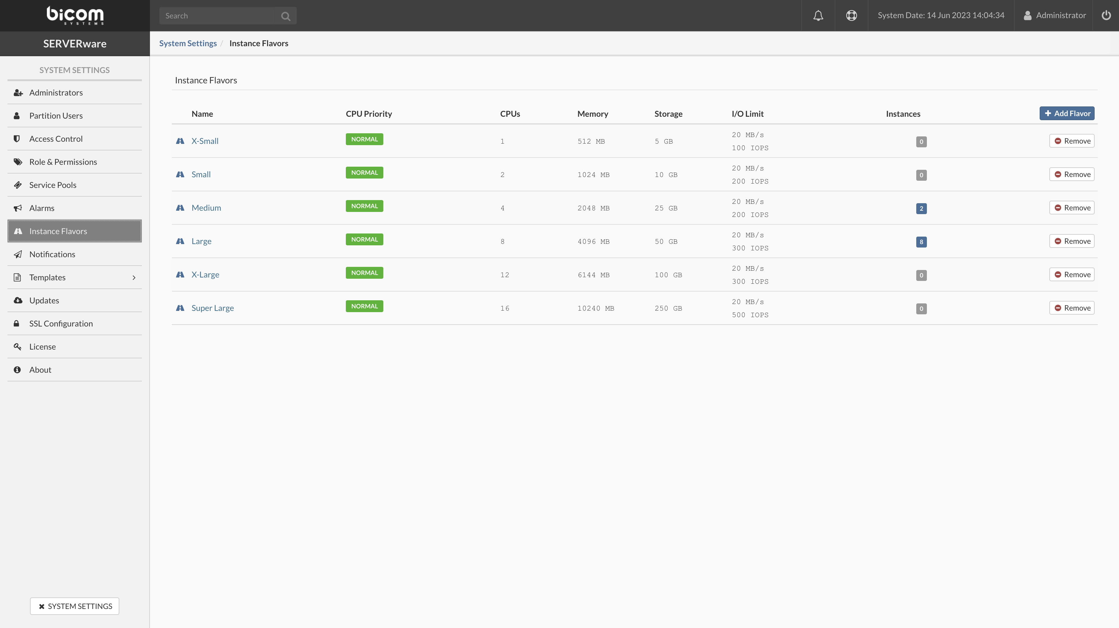
¶ Adding flavor
To add a flavor, do the following:
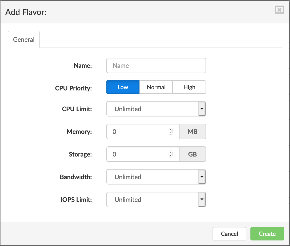
¶ Removing flavor
Follow this procedure to remove a flavor:
¶ Notifications
SMTP/XMPP notification delivery settings can be configured in the **Notifications** section of System Settings.
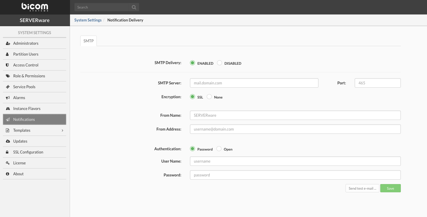
To properly configure SMTP settings, enter all the relevant SMTP data, and then click Save. Configured settings can be tested by clicking the Send test e-mail button. If there is a need to configure SMTP notification delivery using an SMTP server that does not require user credentials for authentication, change the Authentication to "Open". If the SMTP server does not support SSL from the start, change the Encryption type to "None". When encryption is "None", SERVERware SMTP client will automatically switch to the encrypted mode if STARTTLS mode is supported by the SMTP server, otherwise, the connection will stay unencrypted. In case the sending of a test mail fails, the corresponding error message will be visible through the system logs view.
¶ Templates
Templates are software packages used to initialize and deploy new VPSes from. For example, if you want to deploy a PBXware VPS on your SERVERware setup, you will use PBXware template to create a VPS from.
Installed Templates section in System Settings can be used to install and/or remove SERVERware VPS templates. There are 2 template types: Service Templates and System Templates.
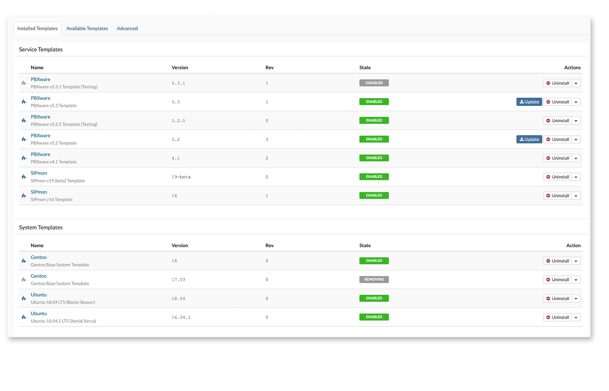
Select Available Templates tab to view available templates, this is the list of available templates for installation (do not install templates that will not be used) .

¶ Installing new templates
To install a new template from the catalog, select the Available templates tab, click on Install. Template download starts right after the confirmation window.
When downloading templates, if multiple templates are selected for download, SERVERware will start downloading first one, and put others into a queue.

¶ OCI image Template
SERVERware supports the third-party OCI images to be used as the template in the SERVERware infrastructure. Users can download the OCI images from the Docker Hub or the local/private repository as long as the OCI images are created according to the Hub Public rules.
An OCI runtime must accept and correctly run (create/start/terminate/delete) a conforming OCI image. An OCI Image contains metadata about the contents and dependencies of the image including the content-addressable identity of one or more filesystem layer changeset archives that will be unpacked to make up the final runnable filesystem.
KVM OCI images are not supported.
¶ Download OCI image
To download the OCI image in SERVERware go to the right main menu and select Templates / OCI Image.
In the newly open windows press the blue button in the upper right corner Install New template
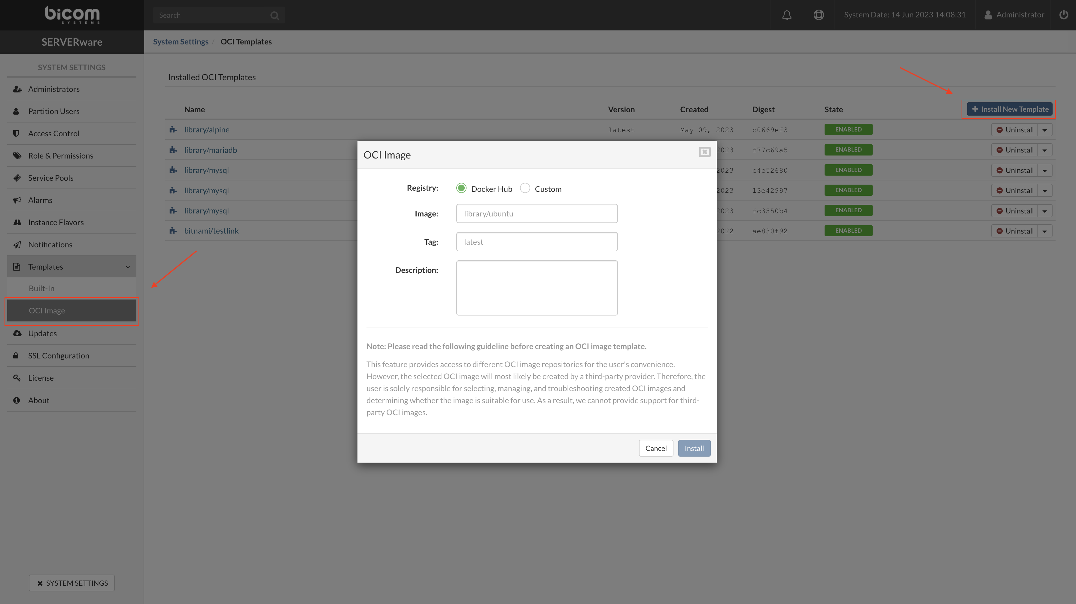
In the popup window enter all required fields and press Install.
SERVERware will download the OCI image and install it on the system so it can be used to create VPS in the VPSs menu.
¶ Updates
Updates section of System Settings is used to update the various SERVERware components. The list on the right side shows the Name, Current Version, and the Latest Version of the component that can be updated.
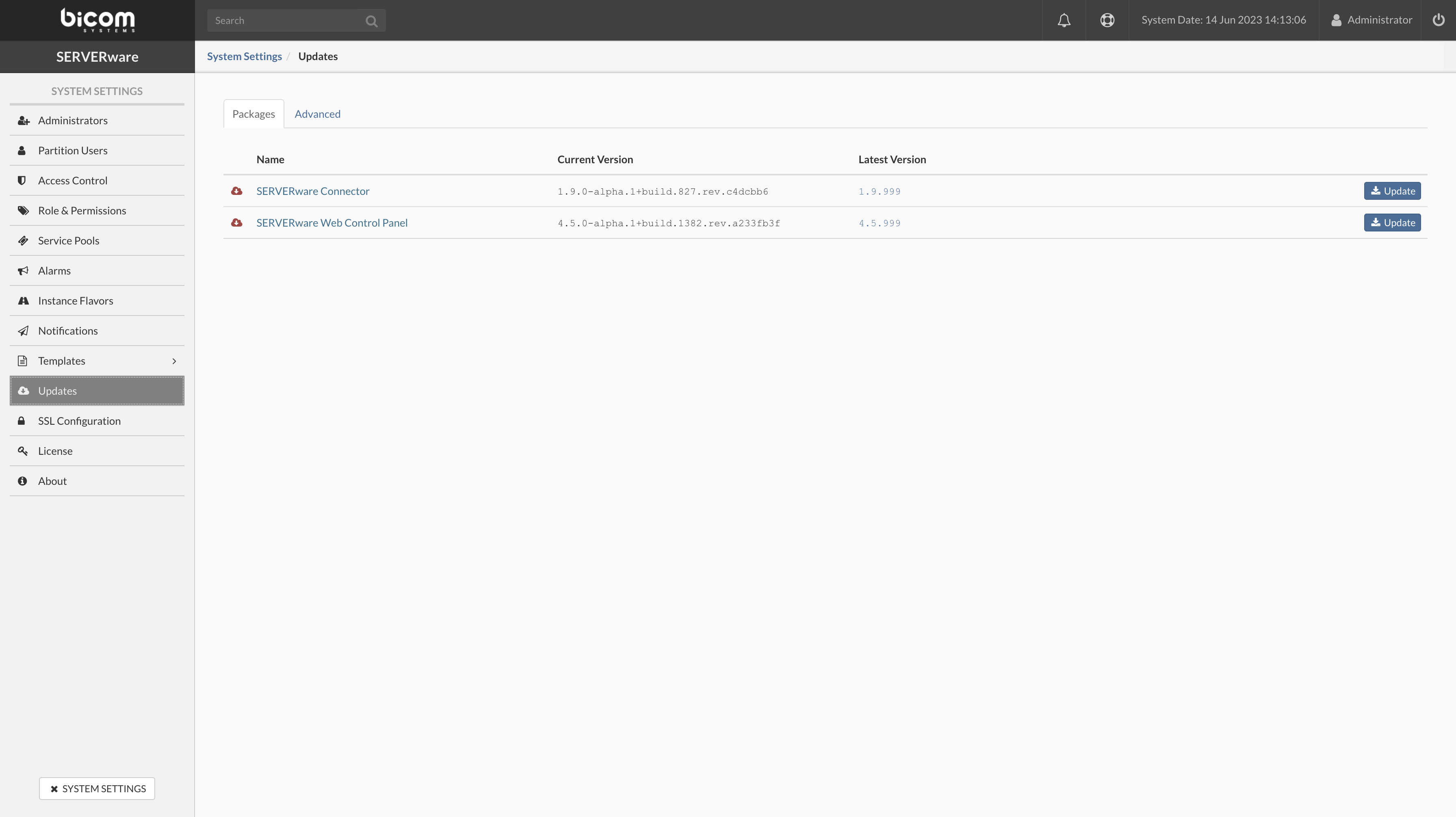
The SERVERware controller will check for available package updates on a daily basis. Once the update is available the notification pop-up message will appear on the top of the GUI screen every time the admin user logs in. The pop-up dialogue window disappears after 10 seconds and provides a link to open the package update view if the administrator wants to proceed with updates.
Email notifications for new available updates will be sent to the system administrators as well.

To update a SERVERware component, click the Update button for that component. The update process starts after the confirmation window.
If there is more than one component update, the SERVERware connector should be the first component to be updated.
Updating Host SW-Connector
The sw-connector service agent running on hosts is a crucial component for the proper functioning of the SERVERware environment, so it has to be updated if there are new features or bug fixes. A host should be moved to maintenance mode before updating the sw-connector.
Follow this procedure to update sw-connector:
¶ SSL Configuration
SSL works by ensuring that any data transferred between users and websites, or between two systems, remains impossible to read. It uses encryption algorithms to scramble data in transit, which prevents hackers from reading it as it is sent over the connection. This data includes potentially sensitive information such as names, addresses, numbers, or other financial details.
The SSL Configuration page show details about the current SSL certificate and option to upload a certificate manually, generate CSR and automatic obtaining of free LE certificate. Let’s Encrypt is a free, automated, and open certificate authority (CA), run for the public’s benefit. It is a service provided by the Internet Security Research Group (ISRG).
SSL on SERVERware GUI can be installed in two different ways. One way is automatic SSL Let’s Encrypt certificate install, and another is manual install.
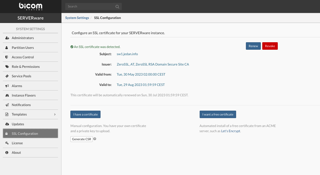
The prerequisite for successful SSL certificate installation on a SERVERware instance is a valid domain name which must point to the public IP address of the SERVERware instance (accessible from the internet and port 80 is open).
To automatically install a free Let’s Encrypt SSL certificate on the SERVERware instance, go to the SSL Configuration menu and click on I want a free certificate button. A popup window will appear:
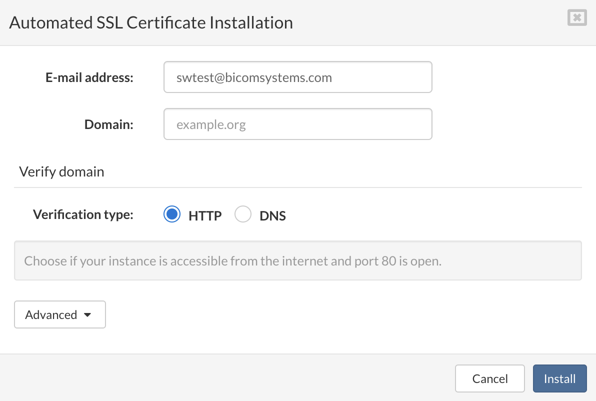
Populate E-mail address and Domain filed and click on the Install button. Wait until the process of installation is complete and GUI will restart to apply changes.
There is also support for ACME servers that require External Account Binding.
We have extended our Automated SSL certificate installation, to support the CA which requires EAB for registering ACME accounts (ZeroSSL, Google Trust Services …)
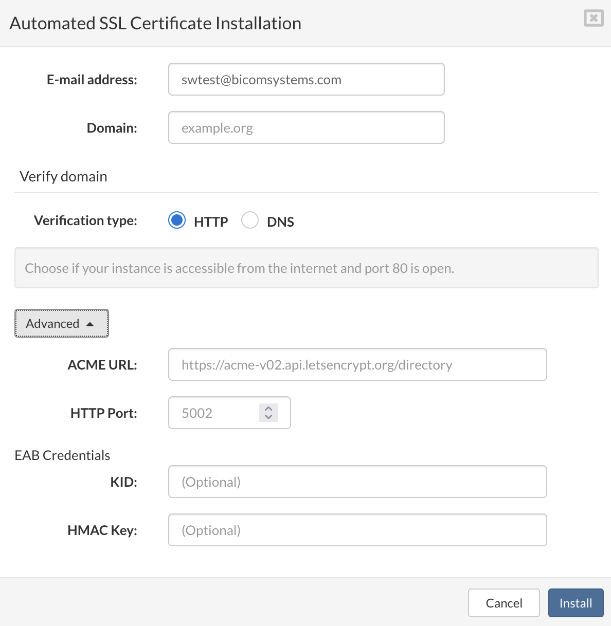
¶ Obtain a certificate using domain verification process
It is possible to automatically install certificate using DNS challenge when SERVERware instance is not publicly available or to use wildcard domain (*.example.org).
This can be accomplished with manual DNS setup or using SERVERware CoreDNS functionality.
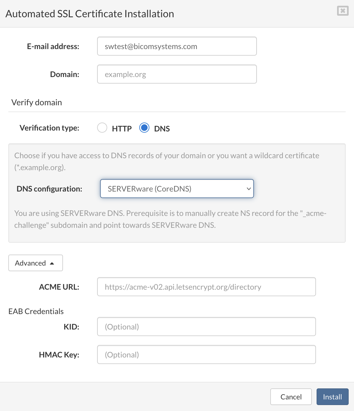
¶ Generating CSR (Certificate Signing Request) from GUI
The CSR is a standardized way to send the issuing Certificate Authority (CA) your public key, which is paired with a secret private key on the server, and provides relevant information about the requester.
This can be done from SERVERware GUI, administrator can generate CSR and a private key for the selected domain and use for purchase of a SSL certificate.
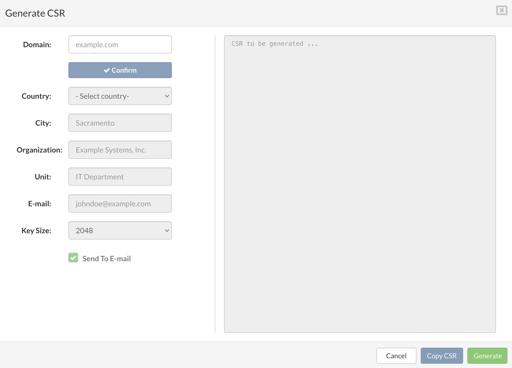
¶ Manual certificate upload and installation
There is an option to upload SSL certificate(and private key) to use instead of self-signed one which is the default.
Upload the .cert file you have obtained from the provider and optionally private key, if private key is not selected the existing key will be used and press Upload.
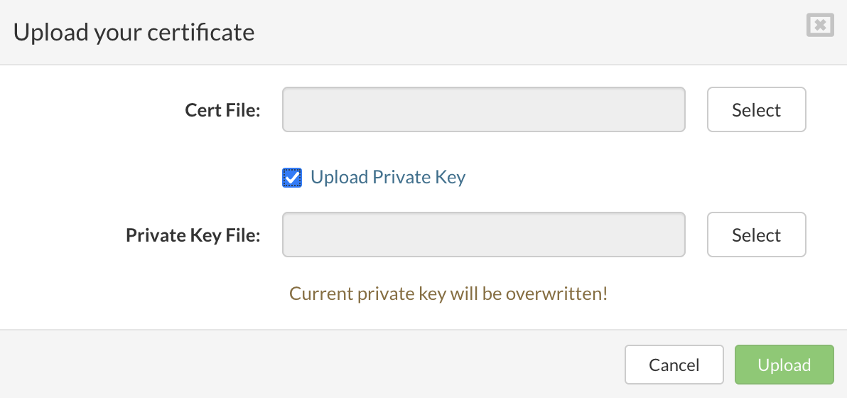
SERWERware will automatically switch to manually added certificate.
¶ Revoke a certificate
Certificate revocation is the act of invalidating a TLS/SSL before its scheduled expiration date. A certificate should be revoked immediately when its private key shows signs of being compromised. It should also be revoked when the domain for which it was issued is no longer operational.
This option is available only if a certificate is generated from Let’s Encrypt, ZeroSSL and similar free providers via automated activation method.
To revoke certificate go to SSL Configuration menu and click on Revoke button.
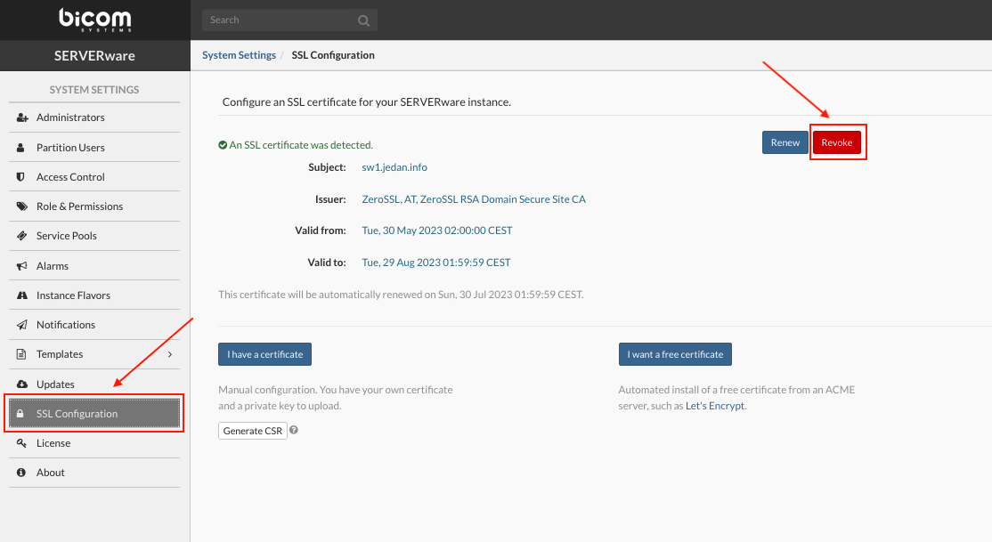
The popup window will appear, select the reason for revocation and click the Revoke button.
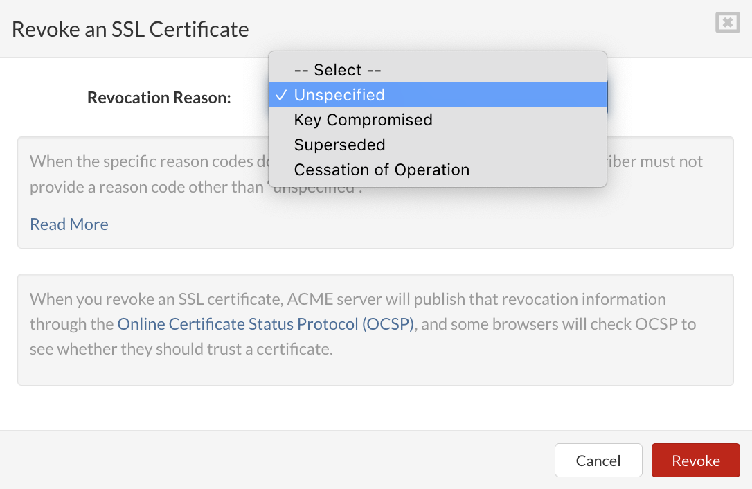
¶ Manual renewal of active ssl certificate
It is also possible to start the certificate renewal process manually.
This option is available only if a certificate is generated from Let’s Encrypt, ZeroSSL and similar free providers via automated activation method.
To renew manually certificate go to SSL Configuration menu and click on Renew button. The popup window will appear, click the Renew button.
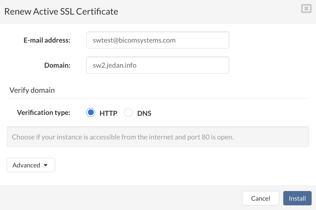
Wait until the process of renewal is complete and GUI will restart to apply changes.
¶ License
License menu shows details about installed SERVERware license and gives you the ability to update or change the license.
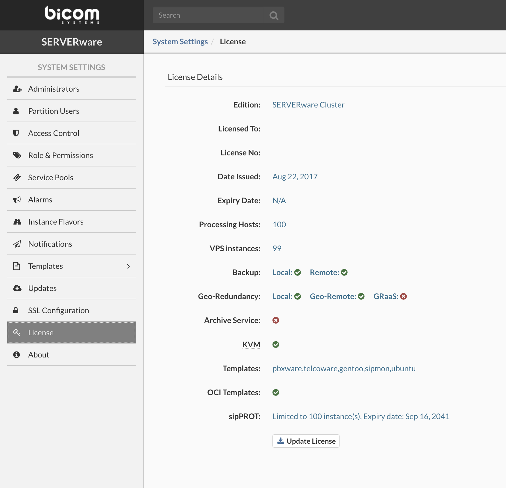
If your license has changed, to update the license, click Update License, enter a valid license number in the text box and click Apply. This will refresh the feature list supported on your instance of SERVERware.