¶ Introduction to Cluster Edition
In today's always-on world, keeping services available and responsive is more important than ever. That's where clustering comes in. A cluster is a group of connected servers that work together as a single system. If one server fails, the others take over — minimizing downtime and keeping everything running smoothly. This makes clusters ideal for critical systems where availability and reliability are essential.
¶ What Is SERVERware Cluster Edition?
SERVERware Cluster Edition is Bicom Systems' most advanced and resilient virtualization platform. It builds on the capabilities of the Standalone and Mirror editions, but takes things a step further by separating storage and compute roles and distributing workloads across multiple hosts. The result is a highly available, scalable system that's built for service providers, telecom operators, and businesses that need to deliver consistent uptime to their users.
¶ How It Works?
At the heart of the Cluster Edition are two storage servers running ZFS, mirroring each other in real time over a dedicated network. Virtual machines (called VPSs) are stored on these mirrored disks and served over NVMe or iSCSI to one or more separate processing hosts. This design means that even if one storage server fails, the other can take over instantly — with no interruption to running services.
Processing hosts don't store data locally. Instead, they connect to the mirrored storage over a fast, dedicated network. This separation makes it easy to scale: just add more processing hosts as your needs grow.
¶ Why Choose Cluster Over Standalone or Mirror?
| Edition | Description (with Pros & Limitations) |
|---|---|
| Standalone | All-in-one server setup. Simple and cost-effective, but has a single point of failure — if it goes down, all services are interrupted. |
| Mirror | Two-server setup with real-time data mirroring. Offers basic redundancy and failover. However, it's limited to just two nodes and doesn't support horizontal scaling. |
| Cluster | Advanced setup with mirrored storage and separate processing hosts. Highly available and scalable, ideal for enterprise use. More complex and requires careful planning and dedicated networking. |
Cluster Edition delivers the best of both worlds: enterprise-grade fault tolerance and the flexibility to grow. It's designed for Managed Service Providers (MSPs), telecom carriers, and IT teams that can't afford to be offline.
With support for automatic failover, shared storage, and distributed processing, SERVERware Cluster Edition provides a solid foundation for delivering reliable hosted services — whether it's VoIP, PBX, or any other virtualized solution.
¶ Hardware Requirements for Cluster Edition
The following guide describes minimal and recommended hardware requirements as well as procedures for a successful deployment of SERVERware Cluster Edition.
¶ Storage/Controller Requirements
| HARDWARE | MINIMUM SYSTEM REQUIREMENTS | RECOMMENDED SYSTEM REQUIREMENTS |
|---|---|---|
| CPU | 2.0 GHz Quad-Core Intel Processor with 8MB Cache | 2.4 GHz Quad-Core Intel Xeon Processor with 12MB Cache |
| RAM | 16GB | 32GB |
| Ethernet | 8 x 1Gb/s network interfaces | 2 x 1Gb/s + 4 x 10Gb/s network interfaces |
| Disk | 1 x 64GB SSD (for system), 2 x 500GB SSD (for storage) | 1 x 64GB SSD (for system), 4 x 250GB SSD (for storage) |
¶ Processing Host Requirements
| HARDWARE | MINIMUM SYSTEM REQUIREMENTS | RECOMMENDED SYSTEM REQUIREMENTS |
|---|---|---|
| CPU | 2.0 GHz Quad-Core Intel Processor with 8MB Cache | 2.4 GHz Quad-Core Intel Xeon Processor with 12MB Cache |
| RAM | 16GB | 32GB |
| Ethernet | 2 network interfaces | 4 network interfaces |
| Disk | 1 x 64GB Solid-State Drive (for system) | 1 x 64GB Solid-State Drive (for system) |
¶ Backup Host Requirements
| HARDWARE | MINIMUM SYSTEM REQUIREMENTS | RECOMMENDED SYSTEM REQUIREMENTS |
|---|---|---|
| CPU | 2.0 GHz Quad-Core Intel Processor with 8MB Cache | 2.4 GHz Quad-Core Intel Xeon Processor with 12MB Cache |
| RAM | 16GB | 32GB |
| Ethernet | 1 network interface | 3 or more network interfaces |
| Disk | 1 x 1TB Hard Disk Drive (for system and backup) | 1 x 64GB Solid-State Drive (for system), 6 x 1TB Hard Disk Drive (backup) (RAID10) |
¶ KVMoIP (Keyboard, Video, Mouse over IP)
One of the hardware requirements for the Cluster edition includes support for remote management and access.
The following requirements are essential for proper functionality:
- Remote power management support (remote reset/power off/on): Enables the ability to remotely control the server's power state, including resetting, powering off, or powering on the system.
- Remote access to BIOS: Allows remote entry to the server's BIOS settings for configuration or troubleshooting without physical access to the machine.
- Remote SSH console access: Provides secure command-line access to the server over SSH, facilitating remote management and operations.
- A public IP assigned to KVMoIP: Ensures the Keyboard, Video, and Mouse over IP (KVMoIP) functionality is accessible remotely via a public IP address.
- If KVMoIP is behind a firewall/NAT, the following ports must be opened: TCP (80, 443, 5100, 5900-5999)
¶ Installation Media Options
Users can utilize the following installation media options:
- A DVD image burned to a DVD and installed via the DVD drive.
- A USB image burned to a USB drive and installed via the USB port.
To ensure the stability and reliability of the server, it is crucial to consider key hardware precautions that help protect against potential data loss. These include maintaining a functioning RAID battery and securing a reliable power supply system.
¶ RAID Battery Importance
A working RAID battery is essential for protecting data in case of a power failure. RAID controllers use cache memory to temporarily store write data, which speeds up the process. However, if the system loses power before the data is written to disk, it can result in data loss.
A RAID battery backup ensures that data in the cache is safely written to the disk once power is restored. To maintain reliability, it's recommended to replace RAID batteries every three years.
¶ UPS and Dual Power Supply Importance
Power loss during data storage can result in data loss. To prevent this, storage servers should be equipped with a reliable power supply, preferably dual power sources or an uninterruptible power supply (UPS).
Dual power supplies (PSUs) ensure that if one power source fails, the other will take over, maintaining a continuous, stable power supply to protect against data loss during power disruptions.
NOTE: Please note that Software RAID (including motherboard) implementations are not supported and could cause potential problems that Bicom Systems cannot support.
¶ Deployment Guide for Cluster Edition
¶ Architecture Overview
- Storage Layer
-
Comprised of two servers with ZFS-managed disks, mirrored in real-time over a dedicated Replication Area Network (RAN).
-
ZFS ensures data integrity with end-to-end checksums and automatic self-healing, correcting silent data corruption across mirrored copies.
- Processing Hosts
-
One or more separate machines run the VPS workloads.
-
These hosts access virtual volumes over NVMw or iSCSI via a dedicated SAN network, not using local disks.
-
If a storage server fails, the mirror takes over seamlessly using shared-floating IP on the SAN.
- Network Topology
-
RAN connects storage nodes directly (≥ 1 Gb/s, low latency).
-
SAN connects storage and processing hosts (also ≥ 1 Gb/s).
-
Floating IP and bonded ports ensure network and link redundancy.
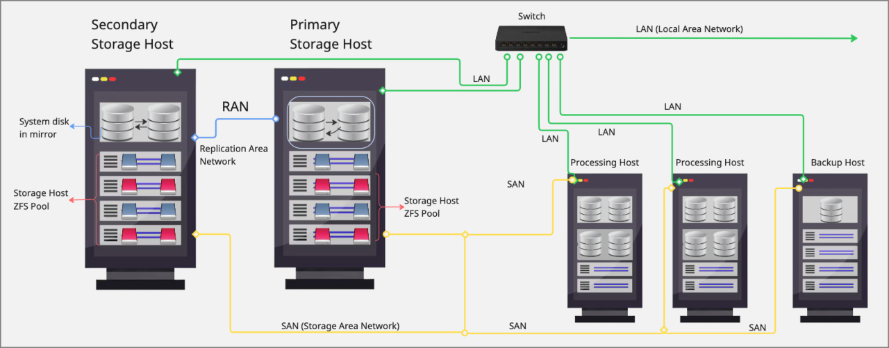
This architecture ensures data redundancy, high availability, and efficient data management through the combination of mirrored system disks, ZFS storage pools, dedicated replication networks, processing and backup hosts, and network connectivity via RAN, SAN and LAN.
¶ Network Setup
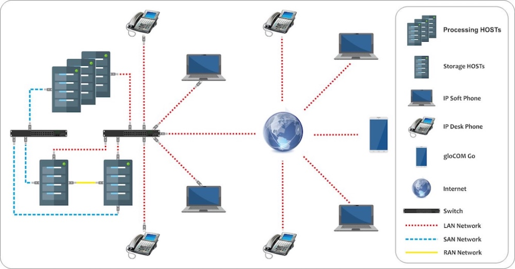
A SERVERware Cluster needs three separate networks to keep things running smoothly and securely. Each network handles a specific type of traffic to prevent bottlenecks and avoid conflicts.
- RAN – Replication Area Network
- Handles real-time data sync between the two storage servers.
- Usually a direct cable or dedicated switch connection.
- Should be isolated from everything else.
- Recommended: at least 1 Gbps, ideally 10 Gbps.
- SAN – Storage Area Network
- Used for iSCSI connections between processing hosts and storage.
- Critical for accessing virtual machine disks.
- Must be fast and reliable – 1 Gbps minimum, 10 Gbps preferred.
- Only processing hosts and storage servers connect to this network.
- A floating IP is used to manage failover between storage servers.
- LAN – Local Area Network
- Used for day-to-day access: management, VoIP traffic, backups, and licensing.
- All components are connected here.
- 1 Gbps is generally enough, depending on service load.
¶ Storage Setup
Storage is the backbone of the cluster. In SERVERware Cluster Edition, it's handled by two dedicated storage hosts using ZFS, a powerful file system known for reliability and data protection.
Because of ZFS's built-in redundancy, hardware RAID is not required. However, if a RAID controller is part of the setup and users choose to use it, both a battery backup and write cache must be enabled. Any hardware RAID configuration lacking battery backup and write cache support will not be supported.
- Storage Hosts (Primary and Secondary)
- Both storage servers run SERVERware OS with ZFS.
- Data is mirrored in real time using ZFS replication over the RAN.
- Drives should be configured in ZFS RAID for better speed and fault tolerance.
- ZFS offers great features like data checksums, automatic error correction, and snapshots.
- Virtual Volumes
- Virtual disks for VPSs are created on the ZFS pool of the active storage server.
- These are shared over NVME or iSCSI to the processing hosts.
- To the VPS, the storage looks like a local disk even though it's remote.
- Backup Host
- Can be a dedicated server or just another system on the LAN.
- It receives scheduled ZFS snapshots from the primary storage host.
- Useful for disaster recovery and long-term storage.
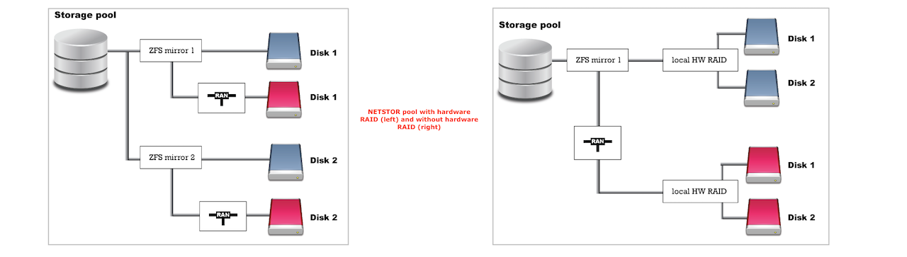
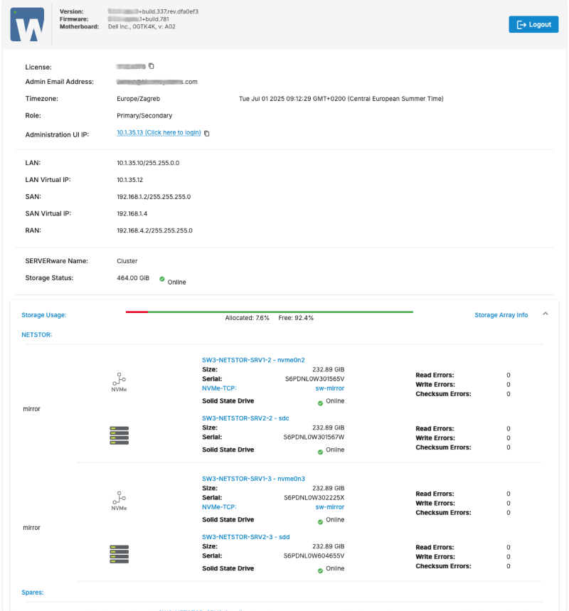
The image below illustrates an example where each server is equipped with two disks dedicated to storage. During setup, the wizard will automatically create a storage pool named NETSTOR using these disks.
¶ Creating USB Installation Media
USB images and detailed instructions for creating and using them are available on the following how-to page.
This guide provides step-by-step instructions to help users prepare the USB drive, ensuring a smooth installation process for the Cluster Edition.
¶ System Installation Wizard - Storage/Controller Host
Before starting the system installation, users must ensure that the physical machine or server is powered on, properly configured, and functioning as expected. The first step is to insert the installation media (DVD/USB), reboot the machine, and select the installation media as the boot device. The following welcome screen appears.
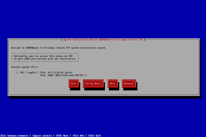
The welcome screen offers several options:
Exit – Select this option to exit the installation wizard and open the live system command line shell.
Verify Media – This option checks the installation media files, compares them against the stored checksum, and verifies their integrity to ensure there is no corruption.
Next – Proceed to the next step of the installation.
Network – Configure the IP address for remote access to the installation wizard.
If the live system successfully obtains an IP address from the DHCP server, it will be displayed on this screen. At this point, the system can be accessed remotely via SSH on port 2020.
Credentials for SSH access:
- username: root
- password: bicomsystems
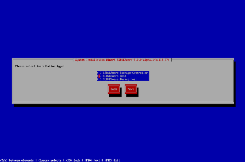
After selecting 'Next,' users will proceed with the installation and be presented with a new window where they must choose whether to install a Storage/Controller Host, Processing Host, or Backup Host.
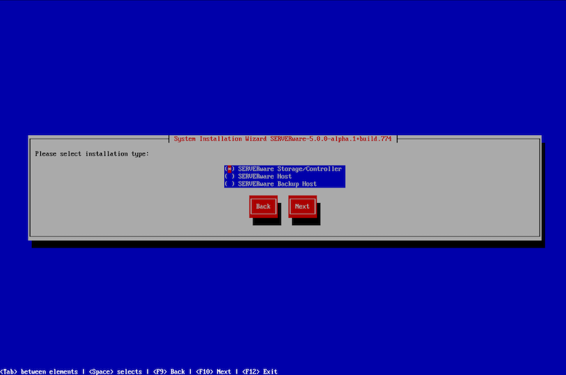
For this example and for installing the Cluster edition, the appropriate choice is the Storage/Controller Host.
After selecting the type of host and clicking "Next", the installation wizard will check for available disks and identify disks available for the SERVERware operating system. If the system is being reinstalled on the same hardware, SERVERware can detect previous installations and will prompt users to restore them.
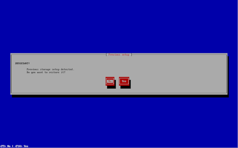
For this example, users should select the "No" option, indicating that they do not wish to restore anything from the ZFS pool.
On the next window, users will select the storage configuration type for the system disk based on the number of detected disks.
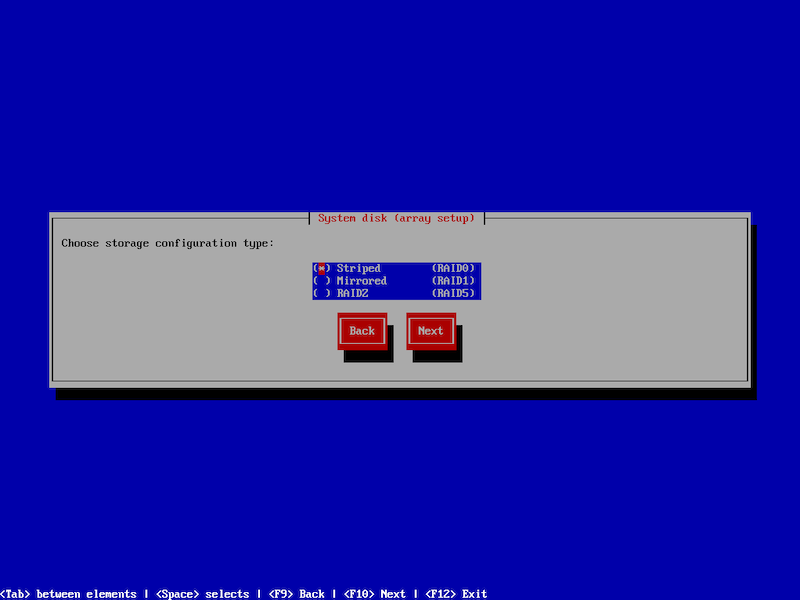
Users can choose from the following storage configuration options:
- Striped – Enhances performance by distributing data across multiple disks, improving read and write speeds.
- Mirrored – Creates a mirrored ZFS pool for increased data redundancy and fault tolerance.
- RAIDZ – Utilizes ZFS RAID-Z technology to provide a balance between performance and data protection.
After selecting the desired type and clicking "Next," users will see the number of detected disks along with available options for creating the system pool. Based on their requirements, they can then choose the appropriate ZFS pool configuration.
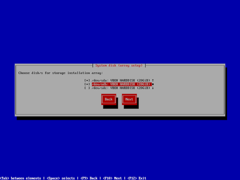
At this step, users can select the physical disk for system installation, where the operating system will be installed. The storage volume, NETSTOR, will be automatically created from the disks not selected in this step.
Multiple disks can be chosen for system installation, depending on the number of disks available in the physical machine.
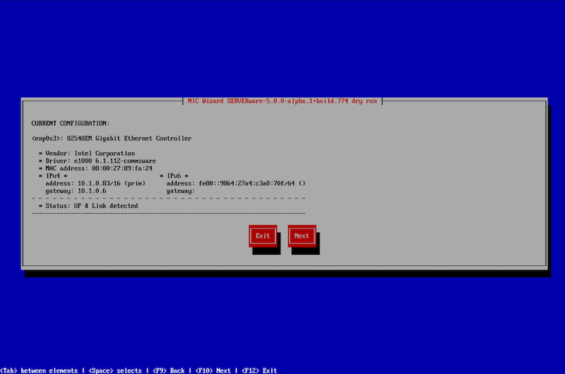
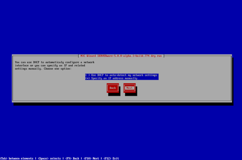
Continuing with the NIC Wizard, users must choose how to configure the selected interface—either by using DHCP to automatically detect network settings or by manually specifying an IP address.
In this example, the IP address will be set manually. To continue, select ‘Next.'
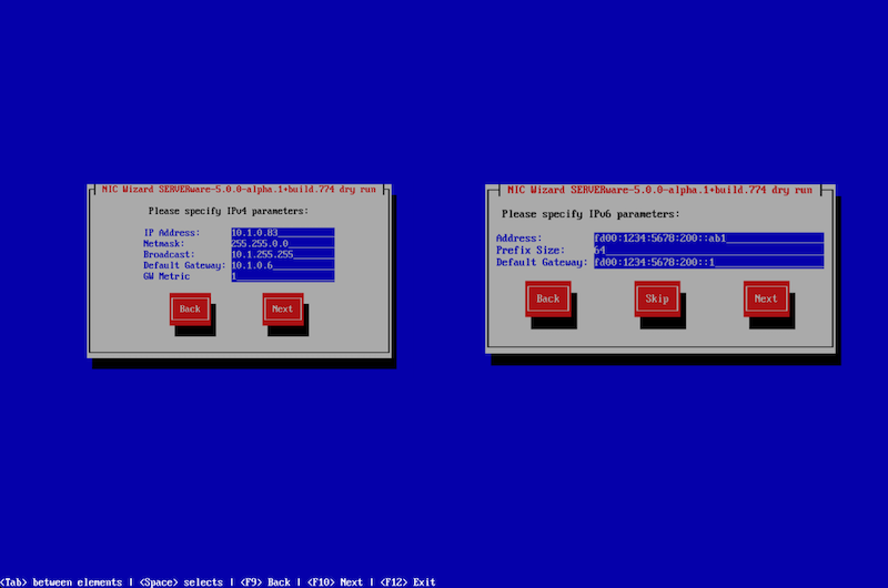
On the following windows, users will have to specify IPV4 and IPV6 parameters.
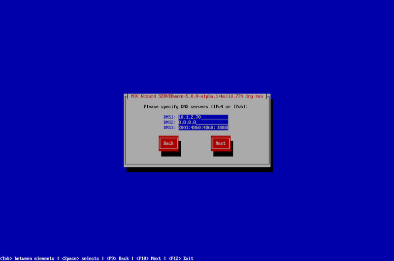
Finally, users will need to set the parameters for DNS.
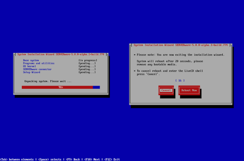
Once the network configuration is complete, click "Next" to begin the installation. The wizard will then proceed with installing the SERVERware operating system and initiate a reboot after the installation is finished.
After completing the installation wizard, the home page will be displayed.
Credentials for accessing the server:
username: swadmin
password: serverware
After installing the first server, referred to as the Primary server, users need to repeat the installation process for the Secondary server. The procedure is the same as installing the Primary server using the setup wizard.
When installing the Secondary server, ensure the procedure exactly matches the Primary server installation using the setup wizard. Any deviation or incomplete setup may lead to configuration errors, data inconsistency, or system malfunction.
¶ System Installation Wizard - Processing Host
Installing a Processing Host using the system installation wizard is just as straightforward as setting up a Storage Host. The only key difference is in the installation type: select SERVERware Host instead of SERVERware Storage/Controller. Aside from that, the process closely follows the same steps as the Storage Host installation.
¶ System Installation Wizard - Backup Host
Installing a Backup Host using the system installation wizard is just as straightforward as setting up a Storage Host. The only main difference is in the installation type: select SERVERware Backup Host instead of SERVERware Storage/Controller. All other steps are nearly identical to the Storage Host installation process.
⚠️ NOTE: A simple SERVERware Cluster setup requires two separate installations for the storage hosts—one as the primary and one as the secondary. In addition, at least one processing host installation and one backup host installation are needed to complete the cluster with full functionality, redundancy, and backup support.
¶ VLAN Tagging with SERVERware
SERVERware simplifies VLAN tagging, an essential feature for servers that need to connect to the internet or specific networks. In many regions, such as South Africa, Australia, and South America, VLAN tagging is a standard part of network setups. Without it, servers may struggle to access the internet or required networks.
This feature is especially helpful when a server has only one physical network connection. VLAN tagging allows the server to connect to both local and public networks at the same time, ensuring smooth operation.
Before setting up a VLAN, users need to remove the br0 (bridge) interface. This ensures that only one physical network interface remains, allowing the creation of VLANs.
To remove the br0 interface, follow these steps:
- After successfully installing SERVERware, open the server terminal and run the command: "netsetup".
- In the window that appears, select "Configure existing network interface" and click Next.
- Select the br0 interface and confirm the configuration by clicking Next.
- On the next screen, choose "Remove this virtual network interface".
After removing the bridge interface, users can begin the process of adding VLANs. Follow these steps to add a new VLAN:
-
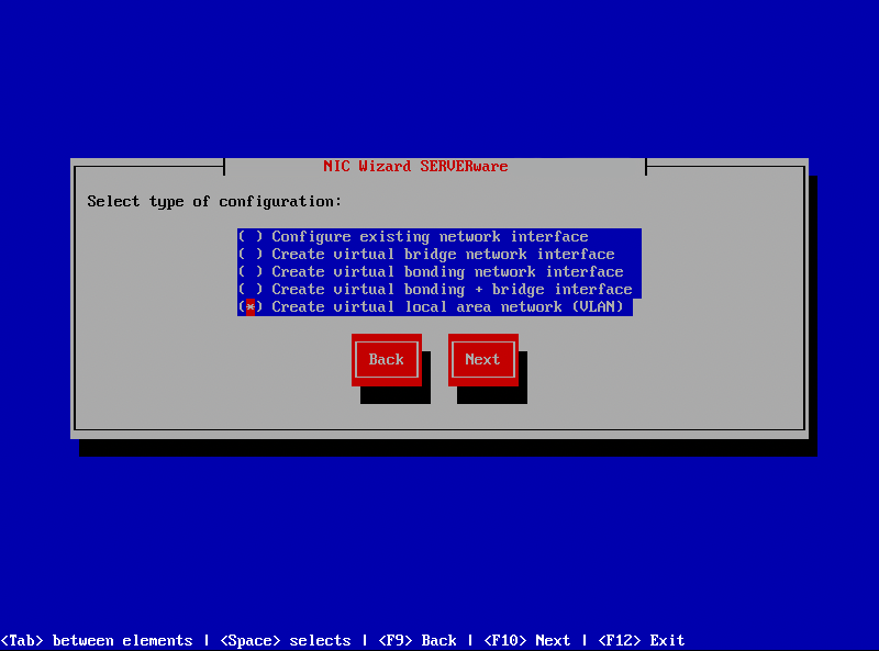
In the terminal window run the command: "netsetup".
-
Select "Create Virtual Local Area Network (VLAN)".
-
Click Next to proceed with VLAN setup.
-
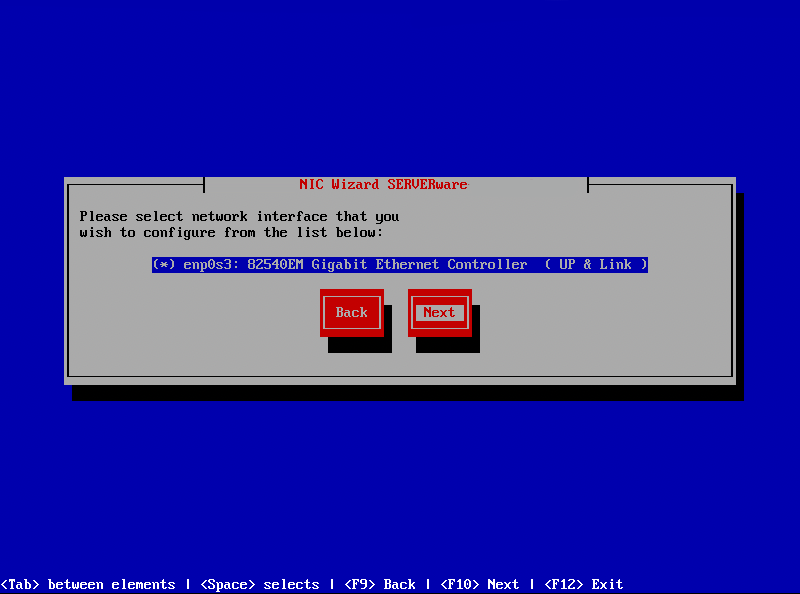
Select the preferred network interface for configuration and confirm the settings.
- On the next screen, users must choose how they want to configure their network interface—either DHCP or Manual configuration.
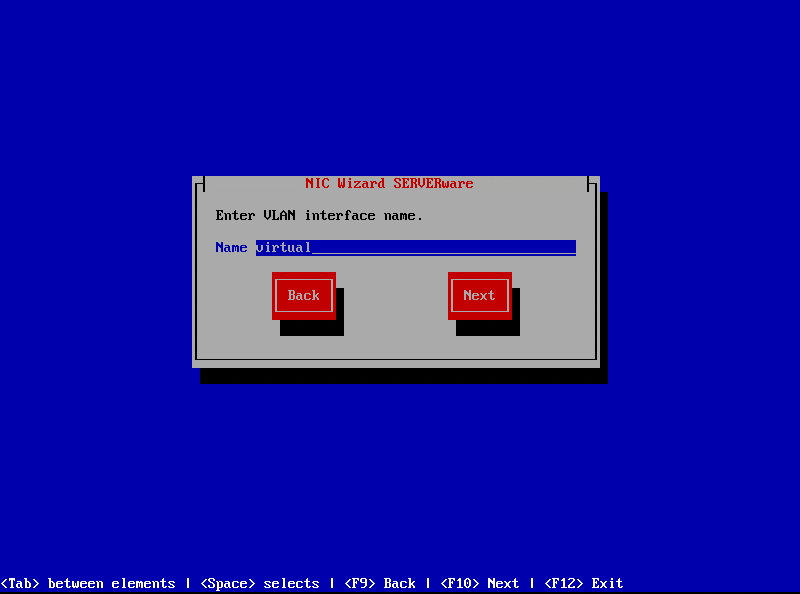
- After completing the configuration, users will be prompted to enter a VLAN interface name. The name must be between 3 and 20 alphanumeric characters (no spaces).
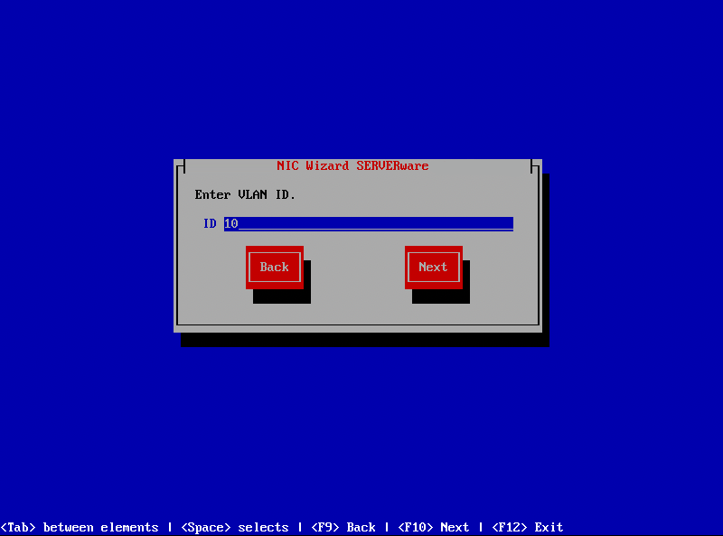
- Enter a VLAN ID within the range of 2 to 4096. VLAN IDs 0, 1, 1002-1005, and 4096 are reserved and cannot be used.
NOTE: Each VLAN ID must be unique, as duplicate VLANs cannot be created.
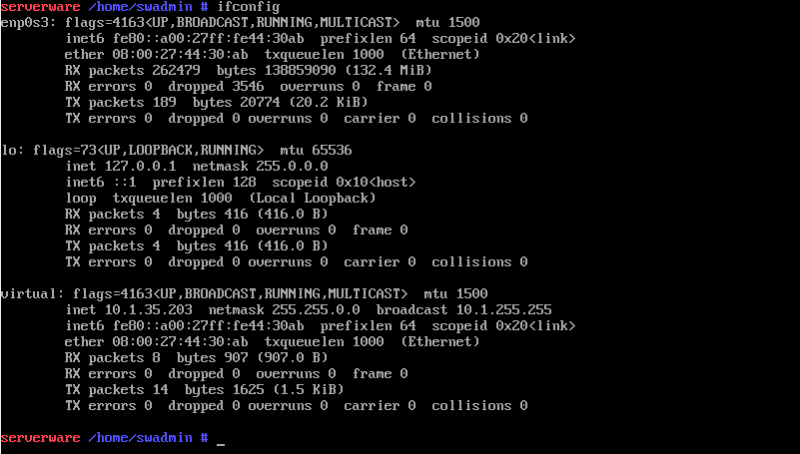
- Once completed, finalize the NIC Wizard and run the command: "ifconfig". This will confirm that the VLAN interface has been successfully created and assigned an IP address.
After successfully completing the installation wizard and configuring the network interfaces, users can proceed with the Setup Wizard installation.
¶ Setup Wizard
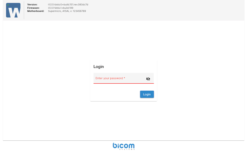
To get started, open a web browser and enter the IP address set during the installation wizard, followed by :81 (for example: 10.1.37.80:81). After accepting the self-signed certificate, the SERVERware Setup Wizard login screen will load. Log in using the default administrator password: serverware.
After successfully logging in, users will be presented with the SERVERware End User License Agreement (EULA). This agreement outlines the terms and conditions for using SERVERware, including licensing rights, usage restrictions, and responsibilities.
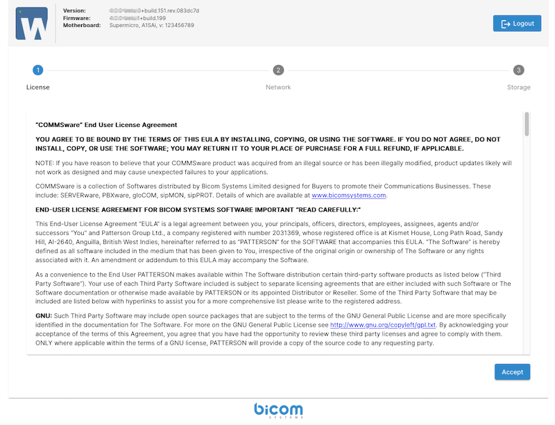
To continue, they need to accept the terms by clicking the "Accept" button. Accepting the EULA confirms that users understand and comply with the stated terms, allowing them to proceed with the SERVERware configuration process.
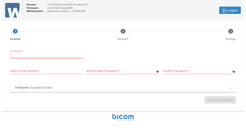
On the next window enter the license number and the administrator's email address, then set a new administrator password for the SERVERware GUI. This password will also be applied to the shell root account, ensuring a unified authentication process. Additionally, select the appropriate time zone to ensure accurate system time and log synchronization. Once all fields are completed, click "Save and Continue" to proceed with the setup.
The next step allows users to configure the LAN network, which is essential for SERVERware management and service provision.
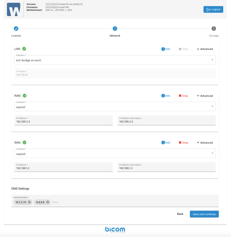
The setup wizard provides default values for the network interface configuration. However, these settings should be carefully reviewed. It is important to verify that all machines are properly connected to their corresponding LAN, RAN, and SAN networks. After confirming that the configuration is correct and all network connections are in place, click Save and Continue to proceed.
On the next window, choose a name for the server if the default name generated by SERVERware is not preferred. The server name must comply with hostname constraints, meaning it should only contain alphanumeric characters and hyphens, without spaces or special symbols.
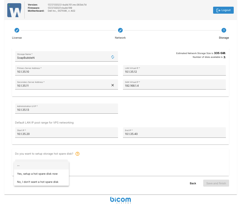
Select the LAN IP address of the second (mirrored) machine from the list or enter it manually (Secondary Server Address). This machine will serve as a mirrored node to ensure storage redundancy and will require additional configuration parameters.
- LAN Virtual IP: This is a floating IP address used to access the mirrored storage server. (will be provided automatically by setup wizard)
- Administration UI IP: This IP address will be assigned to the CONTROLLER VPS, which provides the web-based administrative console.
- Default LAN IP Pool Range: Define a pool range for VPS network. (configured manually)
- Hot Spare Disk: To use this feature, users need to have spare disks available. It functions as a third temporary disk, holding data until the primary disks are physically repaired
Click Save and Finish to begin the initialization and setup of the network storage. The CONTROLLER VPS is automatically deployed on the storage server and is responsible for managing and monitoring SERVERware hosts and VPS instances through a graphical interface. Once the process is complete, a summary of the configuration will be displayed.
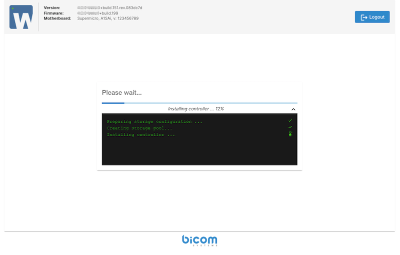
Wait a few moments for the CONTROLLER to start, then click on the Controller Web Console link to begin using SERVERware and creating VPS instances.
¶ SERVERware Cluster Architecture
A SERVERware Cluster environment consists of:
- A redundant Storage server which holds virtual resources like virtual server volumes and templates.
- The Processing Host is where the actual computing happens—CPU and RAM are used to run services like VoIP servers, PBXs, applications, etc.
- Virtual private server's Hosts that use Linux Containers (LXC) is virtualization technology.
- Agents and Tools running on hosts. These tools provide local management for virtual private servers.
- Controller, a centralized management platform for the SERVERware environment. It provides a graphical user interface which can be used to view, provision, and manage resources. It runs on the storage server within a dedicated Linux container.
- A Database that tracks the states and changes of the environment.
- Networking links the environment together. This includes physical network links as well as logical subnets.
The network topology is hown on the following image:
¶ SERVERware Components
The SERVERware environment is structured around two types of resources: physical and logical. Physical resources include components such as storage servers and host machines which provide the necessary hardware foundation. Logical resources, on the other hand, consist of nonphysical elements like domains, logical subnets, and virtual server templates.
The SERVERware Cluster edition consists of several key components that work together to manage virtual infrastructure efficiently:
- Network: The highest-level container that brings together all physical and logical resources, including domains, virtual servers, storage, and network configurations.
- Storage: A centralized shared storage system using ZFS as the storage engine and NVMe or iSCSI protocol.
- Proccesing Host: A dedicated server responsible for running virtual machines (VPS instances). It does not store data locally—instead, it connects to the central storage system over the SAN (Storage Area Network) and accesses virtual disk volumes via NVMe or iSCSI protocol.
- Backup Host: A dedicated server that provides additional redundancy and ensures data protection through backups.
- Logical Subnets: Virtualized network segments used for traffic management and communication between storage and backup hosts.
- Domains: Logical groupings of physical and virtual resources, along with user accounts, to simplify management.
- Virtual Private Servers (VPS): Software-defined servers that function like dedicated physical machines, offering flexibility and easy management.
- Virtual Networks: IPV4 or IPV6-based virtual networks created within SERVERware.
- Templates: Pre-configured VPS setups containing all necessary software, which can be combined to create more specialized environments.
- Backups: Data protection and recovery feature ensuring security and redundancy.
- DNS: A dedicated feature for resolving network services and domains within SERVERware.
- Geo-Redundancy Server (GRS): Allows VPS replication to another remote SERVERware location for enhanced disaster recovery.
- Users: Multiple user accounts with different roles and permission levels for controlled access.
- System Logs: A logging system that records system events, useful for management, troubleshooting, and security auditing.
- Alarms: Alerts triggered by abnormal system conditions, notifying designated recipients through various channels.
- Observability: Enhanced observability features to provide better insight into platform performance and behavior.
- Statistics: Resource usage tracking for both Backup Hosts and VPS, storing and displaying performance data for monitoring and optimization.
¶ Accessing the Web Control Panel
¶ Logging in to the Web Control Panel (Administration UI)
To access the SERVERware Web Control Panel, open a web browser and enter its IP address. If the installation process was followed correctly, this will typically be the Controller/Storage host IP address +1 by default. This will take users to the login screen.
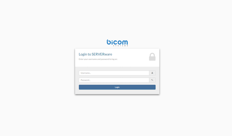
Here, users need to enter the username and password they set during the Setup Wizard installation, then press "Enter" or click "Login".
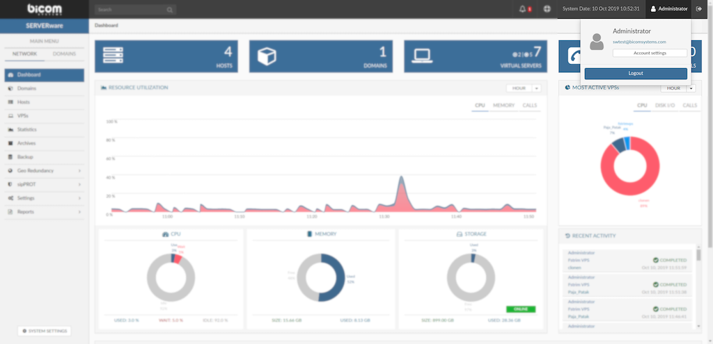
Once logged in, the SERVERware Dashboard will appear in a new window. This document will outline all the features available within the dashboard.
¶ Title Bar
At the top of the SERVERware Dashboard, the Title Bar serves as a powerful tool, providing quick access to essential features and shortcuts.

Titlebar Features (From Left to Right):
- Search Box – Available throughout the SERVERware GUI, allowing users to quickly locate content.
- Notifications – Displays alerts in a color-coded format based on priority. (Refer to the Alarms section for more details.)
- Support Access – Administrators can enable support access for their SERVERware instance with ease. (See the BSSUP section for further information.)
- Date and Time – Shows the current server/system date and time.
- Language Selection – Enables users to switch the GUI language, except for system logs which remain untranslated.
- Account Settings – Provides access to account management options, including password changes, enabling/disabling 2FA, and managing API tokens.
- Logout – Allows users to securely log out of the SERVERware GUI.
¶ Enable 2FA for SERVERware
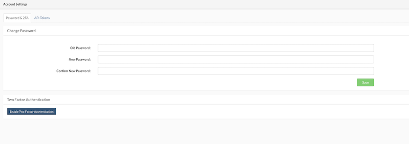
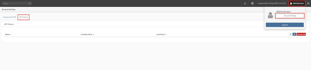
By clicking on the username (Administrator) in the top right corner of the Title Bar and selecting Account Settings, users can access the Account Settings menu.
In the "Two Factor Authentication" section, users can enable Two Factor Authentication.
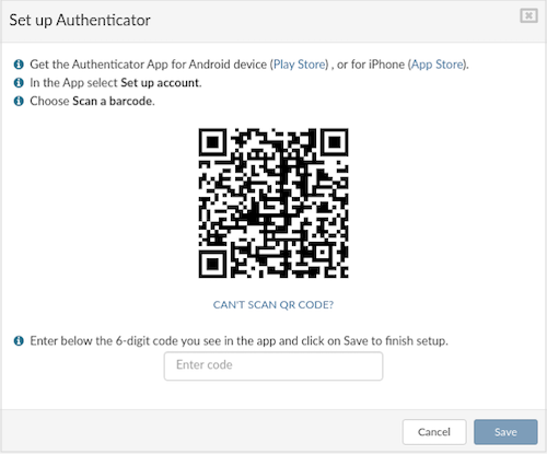
Follow the instructions from '''Set up Authenticator''' window and click '''Save'''.
On this step, users can disable 2FA or view Backup Codes. This window also serves as confirmation that 2FA has been enabled for the specific user. Additionally, users can Change Password at this step. Once finished, click Close.
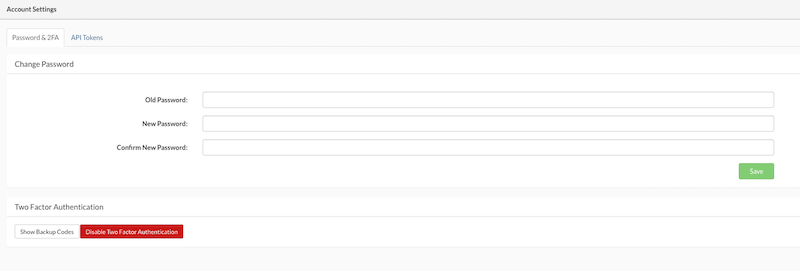
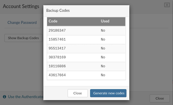
If the Authenticator App is not working or unavailable for any reason, Backup Codes can be used. Click on Show Backup Codes to view the available codes. A new popup will appear displaying the list of codes and their status (used or unused). Each code can only be used once. If no codes are available, new codes can be generated by clicking on the Generate new codes button.
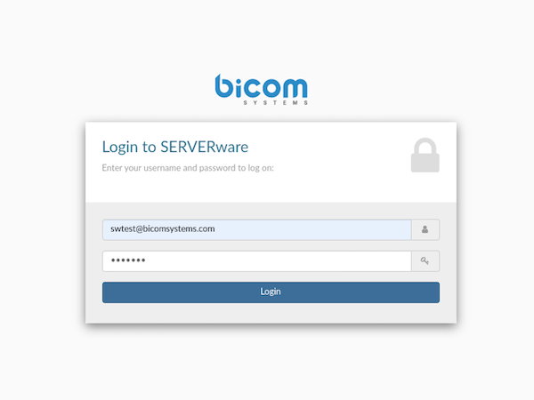
To start using 2FA, log out of the SERVERware panel. The login screen will appear. Enter the username and password, then click Login.
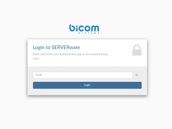
If the entered username and password are correct, a new screen will appear. If the username or password is incorrect, an error message "Invalid Credentials!" will be displayed. To complete the login procedure, enter the code from the Authenticator app or an unused backup code.
¶ API Tokens
The API Tokens allows users to generate and manage API tokens for accessing and interacting with the system. API tokens provide a secure way to authenticate and authorize third-party applications or services to use the system's APIs.
By providing a user-friendly interface for creating, managing, and securing API tokens, users can leverage this feature to integrate and interact with the system programmatically while maintaining a high level of security and control.
¶ Accessing API Tokens
To access the API Tokens feature, users should follow these steps:
-
Navigate to the Account Settings section.
-
Open the API Tokens tab within the Account Settings interface.
¶ Creating a New API Token
To create a new API token, users can follow these steps:
-
Open the API Tokens tab in the Account Settings.
-
Locate the Add New Token functionality, typically represented by a small cross mark icon in the right corner of the interface.
-
Click on the Add New Token icon to initiate the token creation process.
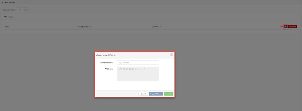
-
Provide a meaningful name for the token to help identify its purpose.
-
Click Generate to create the token.
-
The system will generate a unique API token that can be used for authentication and authorization purposes.
-
Click Copy API Token. Clicking this button allows users to copy the generated API token to their clipboard for easy usage..
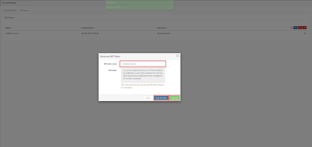
- Close Clicking this button saves the API token, associating it with the user's account for future reference and usage.
¶ Managing API Tokens
Users can manage their API tokens by:
-
Viewing: Displaying the details of each generated API token, including its name, permissions, and associated metadata.
-
Editing: Modifying the tokens is not possible the only way to replace the tokens is to delete existing and create new one.
-
Permissions: When creating tokens, the system automatically assigns the same permissions as the user who created the token.
-
Deleting: Removing an API token to revoke its access and render it unusable.
¶ API Token Best Practices
-
Keep Tokens Secure: Users are advised to keep their API tokens secure and not share them publicly or with unauthorized users.
-
Rotate Tokens Regularly: For security purposes, it's recommended to periodically recreate tokens to ensure they are always up to date and secure.
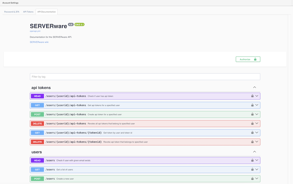
¶ API Documentation
API Documentation tab, providing users with direct access to a Swagger-enabled API documentation page. This page allows users to explore and test API endpoints in real time.
How to Use the API Documentation:
-
Accessing the API Documentation:
- Click on the "API Documentation" button in the GUI. This will open a new browser tab with the Swagger interface displaying the available API endpoints.
- Learn more in our API-Documentation git repository.
-
Authentication Required:
- To execute API calls directly from the documentation, users need to generate an API Key for their user account.
-
Generating an API Key:
- Navigate to the user settings section in the GUI.
Create a new API key and copy it.
- Navigate to the user settings section in the GUI.
-
Using the API Key in Swagger:
- Go back to the Swagger interface.
- Locate the "Authorize" button or the input field for authentication.
- Paste the generated API key into the login prompt to authenticate requests.
-
Executing API Calls:
- Once authenticated, users can select an API endpoint, provide the required parameters, and execute the request directly from the Swagger interface.
¶ Network
¶ Dashboard
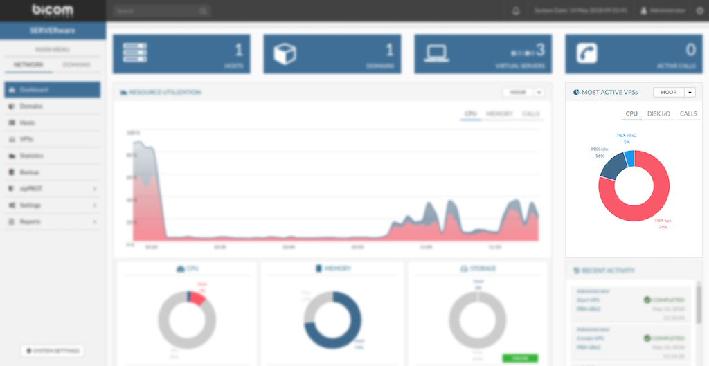
The SERVERware network dashboard provides a visual overview of key performance indicators across the network. Since the storage server plays a central role in the SERVERware environment, many of the dashboard widgets reflect its status and activity.
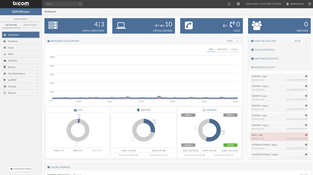
The following is a list of dashboard widgets:
- Running VPSs Indicator - Display the total number of VPSs as well as the number of running VPSs.
- Active Calls Indicator - Display a total number of concurrent calls on all running VPSs within the SERVERware network.
- CPU Usage Indicator - Display CPU usage on primary storage host.
- MEMORY usage indicator - Display memory usage on primary storage host.
- STORAGE Usage Indicator - Display storage usage of a NETSTOR pool.
- Resource Utilization - Display resources usage over time CPU/MEMORY/CALLS, the period of HOUR/DAY/WEEK can be selected.
- Most Active VPS - Display the pie chart of resource usage per VPS.
- Call Statistics - Displays the total number of calls across all VPSs in SERVERware.
- Meeting Statistics - Shows combined data for all meetings across all VPSs in SERVERware.
- Recent Activity List - Display recent activity on SERVERware.
- Local storage - Display status of local storage for all hosts in cluster.
Most Active VPS Chart
The Most Active VPS chart helps administrators quickly identify which VPS is generating the highest I/O load on the system.
Most Active VPS's can be viewed in several time periods:
- HOUR
- DAY
- WEEK
Also, there is a filter by resources used:
- CPU
- DISK I/O
- CALLS
Calls Statistics Dashboard
The Calls Statistics widget displays the total number of calls made across all VPSs in SERVERware, shown over various time periods.
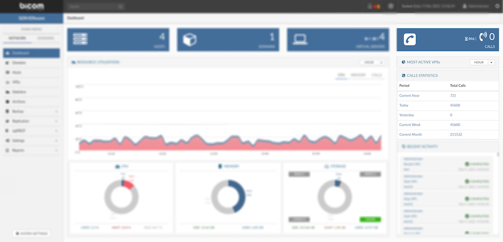
Calls statistics are displayed in several time periods:
- Current Hour
- Today
- Yesterday
- Current Week
- Current Month
Meeting Statistics Dashboard
The Meeting Statistics widget shows combined data for all meetings across all VPSs in SERVERware, presented over different time periods.
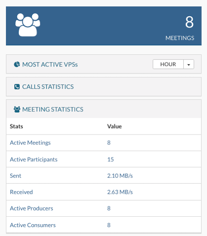
Meeting statistics are displayed in several time periods:
- Active Meetings
- Active Participants
- Sent
- Received
- Active Producers
- Active Consumers
Recent Activity
The Recent Activity dashboard displays a log of the latest actions on the server, such as user logins/logouts, system setting changes, and other key activities.
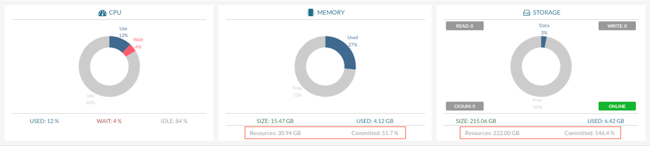
CPU, Memory and Storage Usage
Memory, Storage and CPU dashboard displays over-commit on resources:
-
CPU – Shows the total available CPU resources for host. CPU usage is broken down into Used, Wait, and Idle to give a clearer view of how processing power is being utilized by VPSs.
-
Memory – Refers to total available storage memory for host. The amount assigned to VPSs is shown under Committed as a percentage of the total.
-
Storage – Indicates the total available disk space on host. The portion allocated to VPSs is shown under Committed as a percentage of total storage.
Local Storage
Provides a detailed view of the local storage allocation, showing how storage space is distributed within pool.
In SERVERware's storage pool view, two separate bars indicate the usage of different types of storage space:
-
Logical Used: This represents the real-time amount of space currently in use within the storage pool, reflecting the actual data stored.
-
Used: This shows a larger value that includes both the Logical Used space and any additional reserved space in the pool. In other words, it represents the total of the actual data stored plus any space set aside for system use or future data.
¶ BSSUP
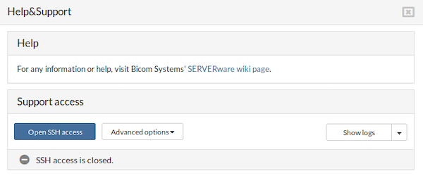
¶ BSSUP Panel
To access the BSSUP panel, click on the button next to the System Date in the top right SERVERware menu. BSSUP's main panel should appear on the right side of the SERVERware web interface. To close it, simply click again on the BSSUP button.
BSSUP panel has a clean and simple design with several buttons:
-
Open SSH access button, for opening SSH access to user's server
-
Advanced options button, to modify SSH port or to set Timeout
-
Show logs button, to access logs.
The status bar is at the bottom of the panel, which is showing whether SSH access is open or closed.
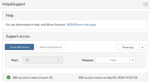
¶ SSH Access
When SSH access is opened, an icon in the status bar changes color into green with the checkmark inside together with the SSH access status, indicating that everything is up and running on port 22. Also, the BSSUP panel button changes color into orange while the SSH access is opened.
Next, to the status information in the status bar, there is also info on when the SSH access will be closed. During this stage, it's not possible to access Advanced options.
¶ Advanced Options
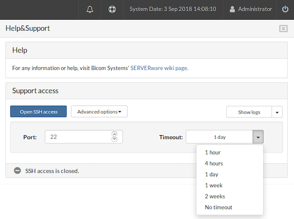
-
The Port field defines which port will be used for SSH access. If an invalid value or non-numeric text is entered, the field will be highlighted in red, and the option to open SSH access will be disabled.
-
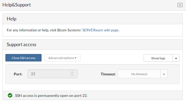
The Timeout dropdown allows selection of the duration for which SSH access will remain open.
For example, entering port 22, selecting No timeout, and enabling SSH access will result in the status bar indicating that the port is permanently open, with no timeout applied.
¶ SSH Access List
Open three separate terminals and in each one execute the command:
ssh root@IP_ADDRESS_OF_CONTROLLER -p22
Afterwards, the display should show the following:
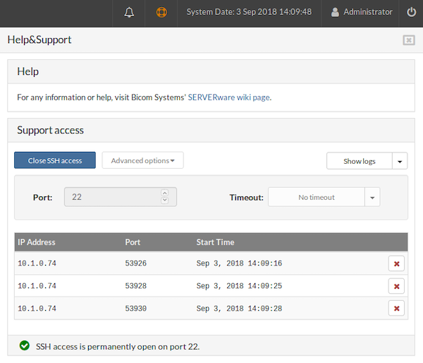
-
The IP Address column lists all IP addresses of computers from which SSH connection requests were made
-
The Port column displays all ports used for these connections
-
The Start Time column indicates when each connection began
At the end of each connection status row, buttons are available to stop individual SSH sessions. Clicking one of these buttons causes the corresponding row to disappear from the table, and a message will appear in the terminal indicating the session has been terminated.
Connection to 10.1.50.10 closed by remote host.
Click on Close SSH access.
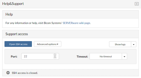
After selecting Close SSH access:
- All active sessions will terminate. Verify in the terminal that all connections have been closed
- The BSSUP panel button at the top will appear gray
- The Advanced options button will be re-enabled
- The Port and Timeout fields will become editable again
- A message in the status bar will indicate that the SSH access is closed
¶ Logs
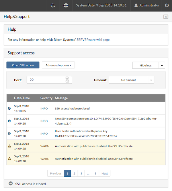
After clicking the Show logs button, the BSSUP panel expands to reveal detailed information about SSH access history, including the date and time, severity, and explanations for each SSH connection:
- The Date/Time column displays the exact date and time when each event occurred
- The Severity column indicates the status of the messages; entries marked as “WARN” feature a yellow background
- The Message column provides a detailed explanation for each log entry
At the bottom of the log list, a page selector is available, accompanied by Previous and Next buttons for navigation.
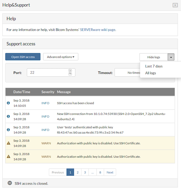
Above the log, a dropdown menu allows selection of the time period for which logs are displayed, offering options for All logs or Last 7 days.
¶ Partitions
A SERVERware Partition is a logical group of physical resources, users, and virtual servers. The main purpose of a partition is to define the administrative boundaries for the management of virtual private servers. A partition can represent an individual, department, or company.
¶ Managing Partitions
The Partitions menu item provides access to a graphical view of all the partitions in the system. The Partitions view consists of a partition list pane and a partition details pane. Users can perform a management task on an individual partition by selecting the partition and then clicking the relevant action button.
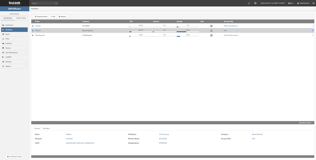
The Partitions landing page allows users to create, edit, or remove specific partitions. At the bottom of the page, there are two tabs: General and Members, which display detailed information about the selected partition.
¶ General Tab
The General tab provides key details about the selected partition:
| Field | Description |
|---|---|
| Name | The partition name. Provide a descriptive name. |
| Company | Provide a company name to which partition belongs. |
| Account URL | An URL to a site or a CRM system containing more details about the company. |
| User Quota | A maximum number of partition members. |
| VPS Quota | A maximum number of VPSs that can be created within the partition. |
| Memory Quota | A maximum amount of RAM memory that can be utilized by the partition VPSs. |
| Storage Quota | A maximum amount of Storage space that can be utilized by the partition VPSs. |
¶ Members Tab
The Members tab lists users assigned to the partition. It displays each member's name, email address, and assigned role within the partition.
¶ Creating Partition
Follow this procedure to create a new partition:
In the "Partitions" view, click the "Create Partition" button. This action will open the "Create Partition" dialog, where users can configure the settings for the new partition.
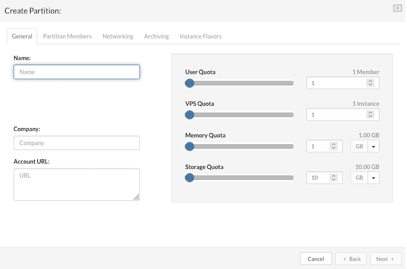
On the "General" tab enter the details in the following fields:
- Name: A descriptive name assigned to the partition for easy identification.
- Company: The name of the company or organization that owns or is associated with the partition.
- Account URL: The website URL of the company can be entered here; this field may also be left blank if not applicable.
- User Quota: Defines the maximum number of users or members that can be assigned to the partition, helping to manage access and resource allocation.
- VPS Quota: Specifies the maximum number of Virtual Private Servers (VPSs) that can be created or managed within the partition, controlling the scale of virtual infrastructure.
- Memory Quota: Sets the total allowable amount of RAM (Random Access Memory) that can be allocated across all VPSs in the partition, ensuring memory resources are used within set limits.
- Storage Quota: Determines the maximum storage capacity available for all VPSs within the partition, helping to control disk space usage and prevent overconsumption of resources.
Click the "Next" button to configure partition members on the "Partition Members" tab.
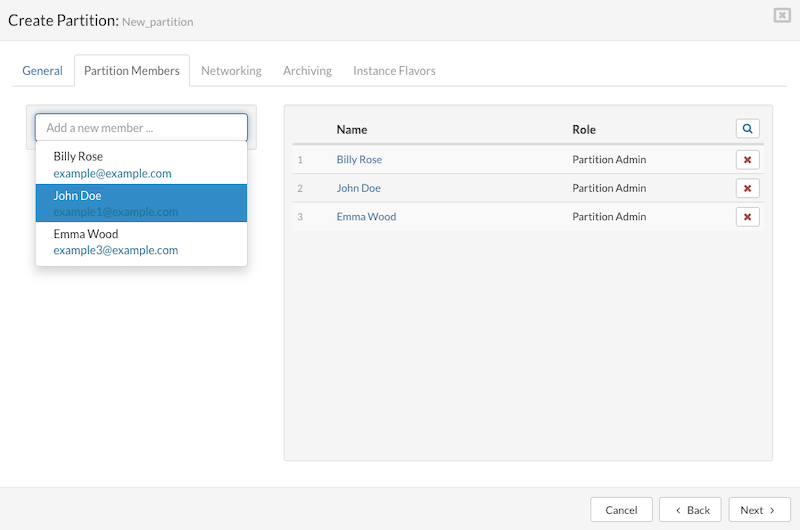
Add Partition Member
To add a user to the Partition Members in SERVERware:
- Navigate to the Partition Members tab.
- Use the dropdown list to select an existing user or search for a specific one.
- Once a user is selected, they will be added to the list of partition members along with their pre-assigned role. Upon their next login to the web interface, access to the assigned partition will be granted, allowing management of the Virtual Private Servers (VPSs) within it.
Remove Partition Member
To remove a user from the Partition Members:
- Locate the user to be removed in the members list.
- Click the Remove Member button adjacent to the user's name.
- A confirmation dialog will appear; clicking Remove will finalize the removal. The user will then be deleted from the partition members list.
After managing the partition members, clicking the Next button will proceed to the Networking tab for configuring partition networking.
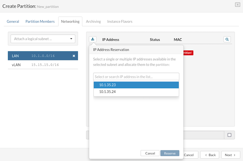
To configure networking for partition VPSs (Virtual Private Servers) in SERVERware:
Selecting a Subnet:
- Navigate to the Networking tab.
- Select the logical subnet intended for connecting the partition VPSs.
Adding a Partition IP Address:
- Click the Reserve Address icon to open the IP Address Reservation dialog.
- Within the dialog, select or search for an available IP address from the list.
- Click Reserve to add the chosen IP address.
- The reserved IP address will then appear in the partition's IP address list.
- If no IP addresses are available for reservation, access the Settings > Networking menu to expand the IP address pool.
Releasing a Partition IP Address:
- To remove an IP address, click the Release Address button located next to the specific IP address.
- A confirmation dialog will appear; click the Release icon to confirm.
- The IP address will then be removed from the partition's IP pool.
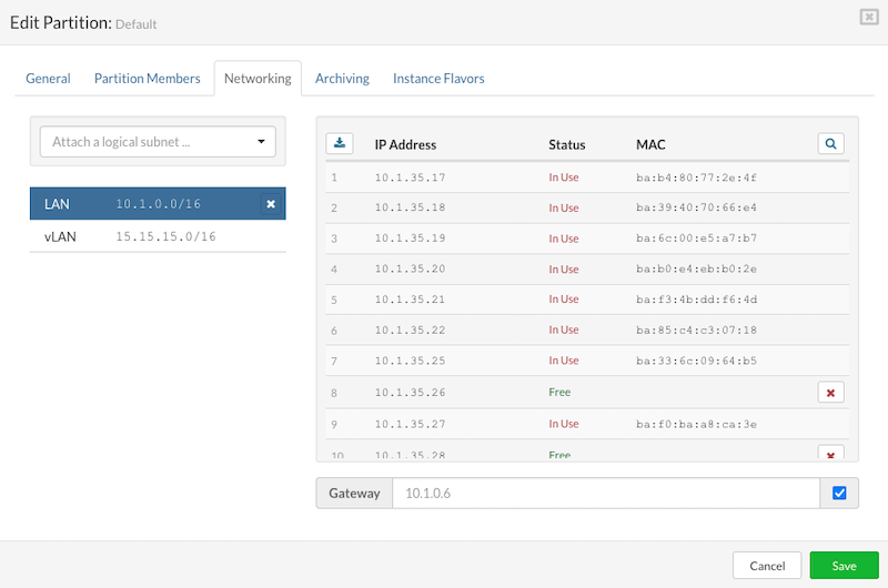
In SERVERware, administrators have the flexibility to choose a different gateway for their network, instead of automatically using the default one. This feature is particularly useful when attaching a subnet to a partition and can be essential for meeting specific Internet Service Provider (ISP) requirements. This allows for the creation of segmented networks in ways that might not be standard, offering more customization to fit unique networking needs.
Click the "Next" button to configure Flavors tab and select resource flavors for partition VPSs.
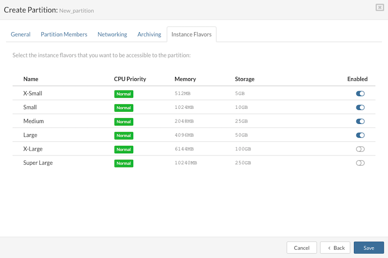
Enable Resource Flavors:
Select the resource flavors to be made available for the partition. These resource flavors define the sizes and capacities of the virtual instances to be used. Ensure that the chosen flavors have been previously configured in the System Settings > Instance Flavors section.
After selecting the desired resource flavors, click the Finish button to initiate the creation of the new partition. Following this, a new entry representing the newly created partition will appear in the list.
¶ Editing Partition
Partition details—such as name, resource quotas, members, networking, and flavors—can be edited.
To edit partition details:
- In the Partition view, select the partition to be modified.
- Click the Edit button to open the Edit Partition dialog (similar to the Create Partition dialog).
- Make the necessary changes.
Click Save to apply and store the updates.
¶ Removing a Partition
A SERVERware partition can only be removed if it contains no VPSs.
To remove a partition:
- In the Partition view, select the partition to be deleted.
- Click the Remove button. A confirmation dialog will appear.
- Confirm by clicking Yes. The partition will then be removed from the list.
¶ Hosts
In SERVERware, a host is a physical 64-bit server running a customized version of Gentoo Linux with everything needed to support virtual servers. There are three main types of hosts, depending on their role:
Storage Host
The storage host is the main part of the SERVERware setup. It provides storage for virtual servers and is usually set up in pairs for redundancy and fault tolerance.
Processing Host
Processing hosts are used to run virtual servers. They rely on LXC (Linux Containers) and don't store data unless needed. These hosts are only used in SERVERware's Cluster editions where tasks are spread across multiple machines.
Backup Host
Backup hosts are optional servers used for storing VPS backups. They add an extra layer of protection and can be used in any SERVERware edition.
¶ Managing Host
The Hosts menu offers a graphical view of all hosts in the system. Users can manage individual hosts by selecting a host and clicking the appropriate action button. Please note, if an action is not available, the corresponding button will be disabled.
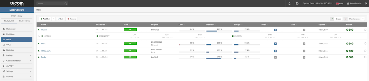
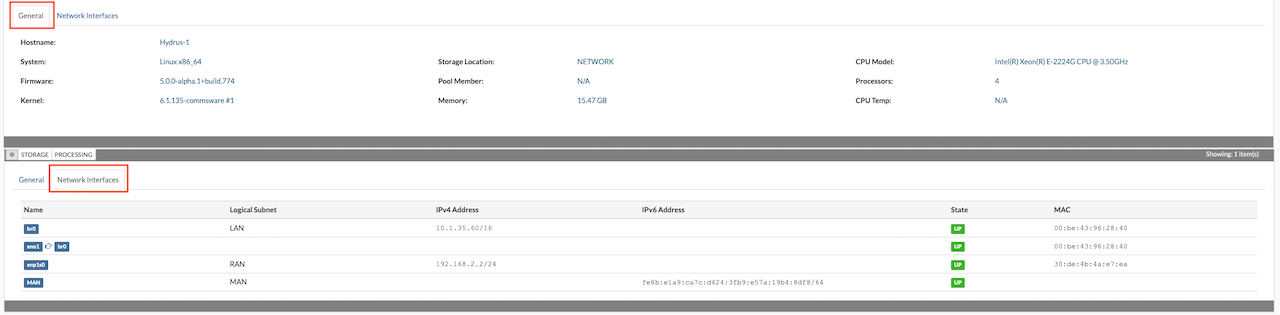
At the bottom of the page, there are the General and Network Interfaces tabs.
- The General tab displays information about an individual host, including hardware and software versions, storage location, available memory, and CPUs.
- The Network Interfaces tab provides details about the host's logical and physical networks, such as interface names, logical subnets (if any), IPv4 and IPv6 addresses, and MAC addresses. This tab also allows the attachment of logical subnets to the host's physical network interface cards.
¶ Adding Processing Host
Hosts must be properly installed before they can be added to the SERVERware virtualization platform. Before proceeding, make sure each host has a correctly assigned IP address. There's no need to manually configure a network bridge—this is automatically created during installation. The network bridge allows virtual servers to communicate with the network as if they were connected directly to a physical network interface.
To add a SERVERware host, follow these steps:
Go to the Hosts section, then click the Add Host button in the Hosts view. This will open the Add Host dialog.
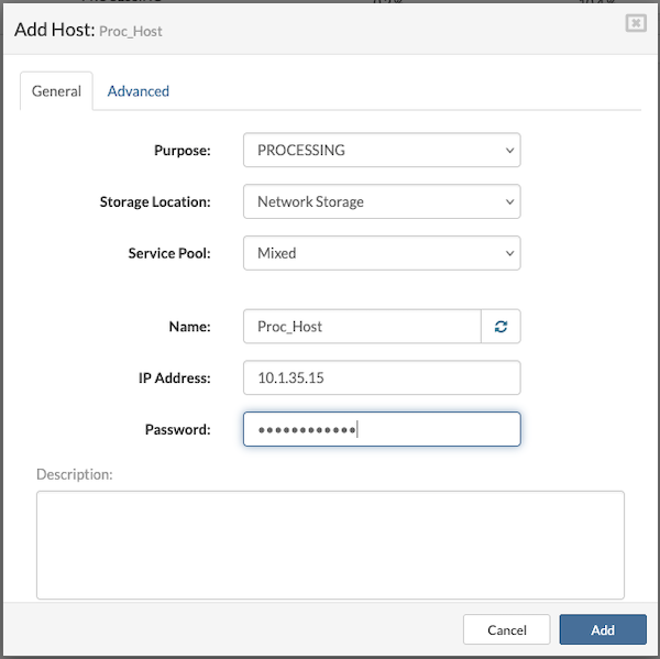
Enter the required information in the following fields:
- Purpose: Defines the role of the host within the cluster.
- Storage Location: Visible only when the host purpose is set to Processing. Select Network Storage as the location for VPS volumes.
- Service Pool: Relevant only for Processing hosts. Select the Mixed pool as the default option.
- Name: A descriptive identifier for the host. A random hostname can be generated using the provided button if a specific name is not necessary.
- IP Address: The IP address assigned to the host during installation.
- Root Password: The root password set on the host. If the default password (serverware) is still in use, a prompt will appear to create a new one after entering it.
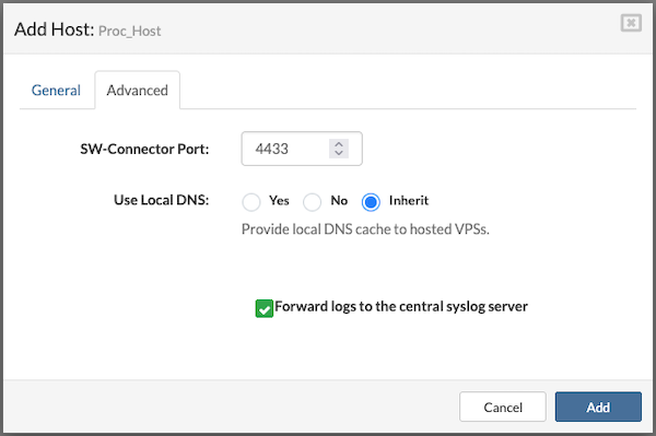
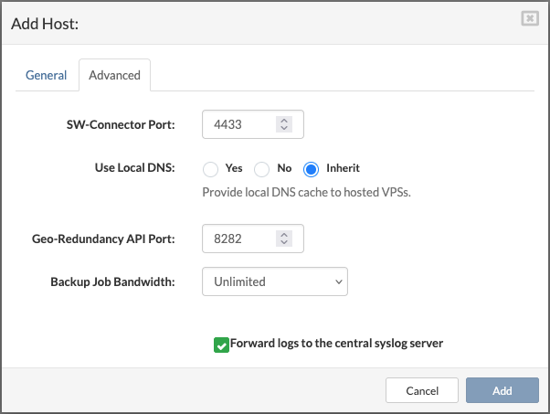
In the Advanced tab, it is possible to modify the SW-Connector Port (default is 4433) and enable or disable log forwarding to the central syslog server by checking or unchecking the corresponding option.
Click the Add button to submit the form.
The newly added host will appear in the host list with a “disabled” status. Health indicators for the Connection and SW-Connector should display green circles, indicating proper communication. The Storage Connectivity indicator will appear as either green or red, depending on whether the host's SAN network interface was pre-configured.
Please note that adding a host with its storage location set to Local (local storage) will result in the Direct storage protocol being used on that processing host (instead of iSCSI or NVMe). Additionally, VPS migration from a host using local storage to any other host will not be possible.
¶ Adding Processing Host with Local Storage
Instead of relying only on networked storage (SAN), the processing host with local storage keeps all of its data on storage devices physically attached to it (e.g., SSDs, HDDs, NVMe drives). A processing host with local storage means a server can do computing and store its data right on its own drives, without relying on a central networked storage system.
Before adding a host to the SERVERware virtualization platform, make sure:
- The host is properly installed.
- A valid IP address is assigned during installation.
Steps to Add a Host
-
Open the Hosts section.
-
Click Add Host to open the Add Host dialog.
-
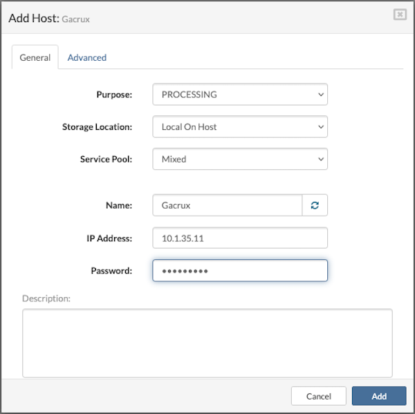
Fill in the required fields:
-
Purpose: Defines the host's role within the cluster.
-
Storage Location: (Visible only if Purpose = Processing). Select Local On Host to store VPS volumes locally.
-
Service Pool: (Relevant only for Processing hosts). Choose Mixed pool as the default option.
-
Name: Enter a descriptive name for the host. User can also generate a random hostname using the provided button.
-
IP Address: Enter the IP assigned to the host during installation.
-
Root Password: Enter the root password set on the host.
-
If the default password (serverware) is still active, user will be prompted to set a new one.
- In the Advanced tab:
-
Change the SW-Connector Port (default: 4433).
-
Enable or disable log forwarding to the central syslog server by checking/unchecking the option.
¶ Adding Backup Host
A Backup host can be added to provide extra data protection in case of a Cluster server failure. Before adding a backup host, it must be properly installed and assigned a correct IP address. Manual configuration of the Network Bridge is not necessary, as it is created automatically during installation. This bridge allows Virtual Servers to connect to the network as if they were using physical NICs.
To add a SERVERware Backup host, follow the next steps:
In the Hosts view, click the Add Host button to open the Add Host dialog.
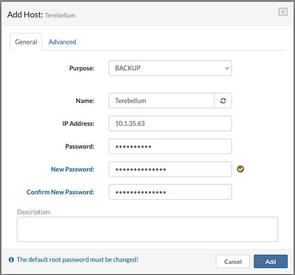
Fill in the following details:
- Purpose: Select the role of the host.
- Name: Enter a descriptive name for the host or use the Generate button for a random hostname.
- IP Address: Enter the IP address assigned to the host during installation.
- Root Password: Enter the host's root password. If unchanged, the default password is serverware. Upon entering the default password, a prompt will appear to set a new one.
In the Advanced tab, users can edit the SW-Connector Port (default: 4433) and configure how the local DNS cache is provided to hosted VPSs. This tab also allows selecting the preferred Geo-Redundancy API port (default: 8282), setting the Backup Job Bandwidth, and choosing whether to forward logs from the backup host to a central syslog server.
Click Add button to submit the form.
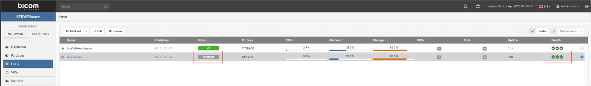
The new host will appear in the host list with a "disabled" state. The health indicators for the connection and SW-connector will show as green circles. If there are any issues with the storage host or backup host, the icons will turn red.
¶ Adding Remote Backup Host
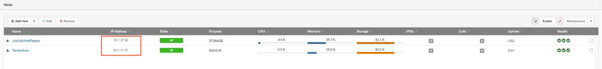
A remote backup host in SERVERware refers to a server connected to an existing storage/controller host but located outside the local network subnet of the primary server. This feature is especially useful when there is an available remote server at another location that can be used seamlessly. If the current backup server is unable to store data due to maintenance, hardware failures, or other issues, SERVERware's capability to integrate remote backup hosts provides a flexible solution for maintaining backups under such conditions.
To add a remote backup host to an existing SERVERware Cluster edition, an additional subnet must be registered for the new backup host. Once the backup host is properly installed and configured, it can be added using the standard host addition procedure.
¶ Enabling Host
After adding, updating, or performing maintenance on a host, it must be enabled before it can be used.
Steps to enable a host:
- Open the Hosts view and select the host that needs to be enabled.
- Click the Enable button. A confirmation dialog will appear.
- Click Yes to confirm.
Once enabled, the host's state will change to UP, allowing virtual servers to run on it.
¶ Maintaining Hosts (Maintenance Mode)
Hosts must occasionally be brought down for maintenance. Users have to manually migrate or stop all virtual servers, before shutting them down. Placing a Host into maintenance mode is a way to notify SERVERware Controller that the host is no longer a stable resource for VPS hosting and cannot be used as a target host for new VPSs as well as a target for VPSs migration or failover.
Follow the below-mentioned steps to move a host into maintenance mode:
- Open the Hosts view and select the host to be placed in maintenance.
- Click the Maintenance button. A confirmation dialog will appear.
- Click Yes to confirm.
The host's State field will change to MAINT (maintenance), and the icon will update to reflect the status. Once maintenance tasks are completed, click the Enable button to bring the host back online. The State field will change to UP, allowing normal operation.
The host status stays unchanged if SERVERware Controller is unable to communicate with and control the host.
¶ Editing Host Details
Users can edit the details of a host, such as its name, password or network configuration.
Follow this procedure to edit host details:
- Open the Hosts view and select the host to be edited.
- Click the Edit button to open the Edit Host dialog.
- Modify the necessary details.
- Click Save to apply the changes.
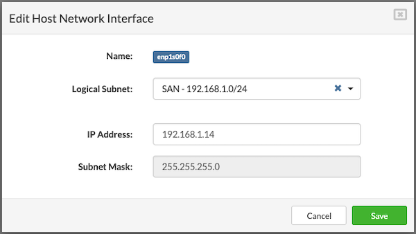
¶ Managing Host Network Interfaces
The Network Interfaces tab in the host's Details pane is used to assign logical subnets to the host's physical network interface cards (NICs). This process involves linking one or more physical NICs to the predefined logical subnets within the SERVERware environment.
SERVERware defines the following three logical subnets during installation:
- LAN (Local Area Network) – Handles SERVERware management traffic and provides network access for VPS services.
- RAN (Replication Area Network) – Used for storage mirroring between the two storage hosts, typically through a direct connection.
- SAN (Storage Area Network) – Manages storage traffic between storage and processing hosts, applicable only in Cluster Edition.
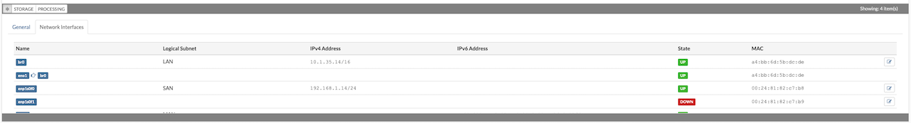
The Network Interfaces tab displays details for each NIC, including interface name, assigned logical subnet, IP address, subnet mask, MAC address, and link status. Each entry includes an Edit button.
By default, the NIC configured during host installation is automatically assigned to the LAN subnet. Since the LAN interface is essential for host management, it should not be edited through the administration GUI.
The RAN interface is used exclusively by storage servers and is configured automatically by the installation wizard.
The SAN interface is required only in SERVERware Cluster Edition. It is automatically configured on storage hosts during setup, but must be manually configured when adding a new processing host.
To edit a network interface:
- In the Hosts view, select the desired host.
- Click the Maintenance button to place the host into maintenance mode.
- Go to the Network Interfaces tab in the Details pane to view the list of NICs and their configuration.
- Click the Edit button next to the NIC to be modified. The Edit Host Network Interface dialog will appear.
¶ Removing Host
Hosts that are no longer in use can be permanently removed. However, only backup hosts can be removed. Before proceeding, ensure that all necessary data stored on the host has been backed up.
Steps to remove a host:
- Open the Hosts view and select the backup host to be removed.
- Click the Remove button. A confirmation dialog will appear.
- Click Yes to confirm. The host will be removed from the list.
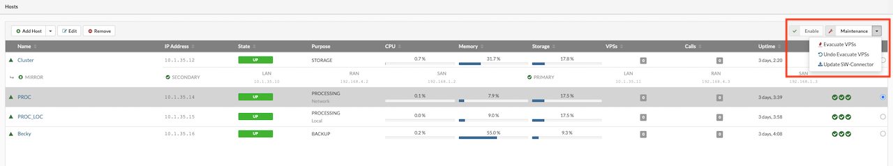
¶ VPS Evacuation
When maintenance is required on a processing host, all running VPS instances can be quickly moved to another host using the Evacuate VPSes option available in the Hosts menu. This eliminates the need to manually migrate each VPS individually. The evacuation process is designed to ensure that all VPSes are restored to their original state once the evacuation is complete.
For the Evacuate VPSes feature to function, the host initiating the evacuation must be set to Maintenance mode.
To evacuate VPSes from a host, follow these steps:
- In the Hosts view, select the host to be evacuated.
- Click the Maintenance button. A confirmation dialog will appear.
- Confirm by clicking Yes. The selected host will switch to maintenance mode.
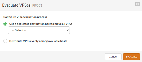
- In the upper-right corner, click Evacuate VPSes.
A dialog box will appear, prompting to either select a specific host to receive the VPSes or to allow the system to distribute them evenly across all processing hosts in the cluster.
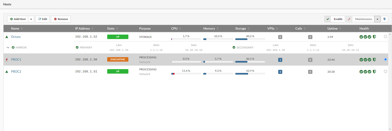
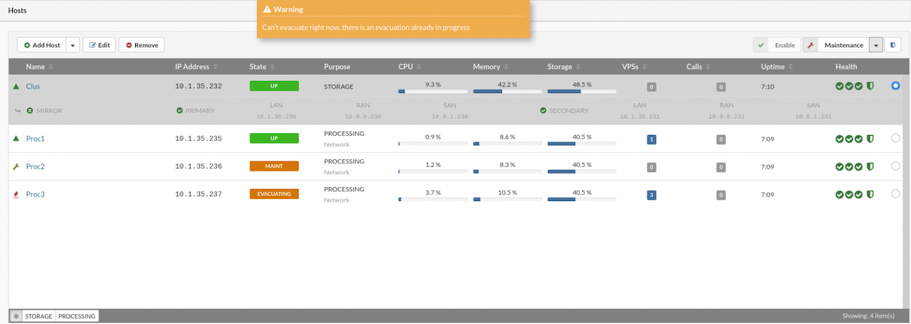
After starting the evacuation, the host's status label will change: the MAINTENANCE label will be replaced by EVACUATING until the process is complete.
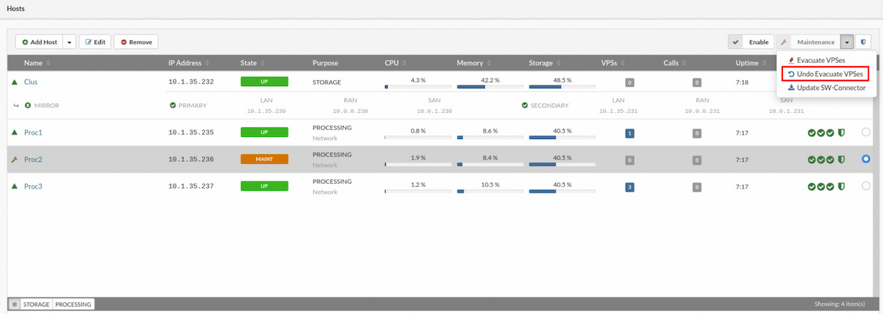
¶ Undo Evacuate Action
The Undo Evacuate action restores the host to the state it was in before the Evacuate VPS operation—this is only possible if the evacuated VPSs have not been moved or deleted after the evacuation.
Example:
If a processing host requires maintenance (such as system updates, HDD, RAM, or CPU upgrades), the Evacuate action can be used to move all VPSs from that host to one or more other hosts, based on the selected option. Once maintenance is complete and the host is back online, the Undo Evacuate action can return the VPSs to their original host in the same state as before evacuation. Any VPSs that were moved or deleted after the evacuation will not be affected by the undo process and must be handled manually.
To initiate the Undo Evacuate process:
- Select the desired host in the Hosts view.
- In the upper-right corner dropdown menu, choose Undo Evacuate.
If the undo action is available, a popup will display the list of VPSs eligible for restoration. VPSs marked as Unavailable will not be affected and must be moved manually.
A confirmation dialog will appear before starting the action. Note that this process may cause some downtime for the VPSs; the duration depends on factors like hardware and VPS size. Once confirmed, the process cannot be stopped until completion. Also, multiple evacuation or undo operations cannot run simultaneously.
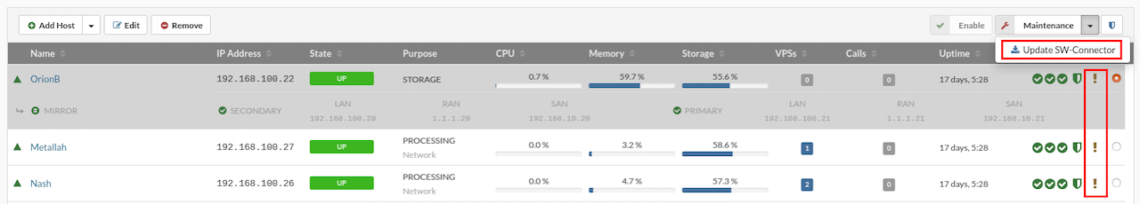
¶ Updating Host SW-Connector
The sw-connector service agent running on hosts is a vital component for the proper operation of the SERVERware environment. It must be updated whenever new features or bug fixes are released. Before performing an update, the host should be placed into maintenance mode.
A small question mark icon next to the host in the Hosts view indicates that a new sw-connector update is available.
To update the sw-connector, follow these steps:
- In the Hosts view, select the host that requires the sw-connector update.
- Move the host into maintenance mode.
- Click the Update SW-Connector button.
- Open the System Logs view to monitor the update progress.
- Once the update is complete, click Enable to bring the host back online.
¶ Virtual Private Servers (VPSs)
¶ Introduction to VPSs
A VPS (Virtual Private Server) is like a small, independent computer inside a larger physical server. It acts like a dedicated server, but it's actually part of a larger machine that shares its resources with other VPSs.
What are they used for?
VPSs are used for a variety of tasks, such as:
- Hosting websites
- Running applications
- Testing and development
- Email servers
How do they work?
VPSs work through a technology called virtualization. Here's how it works in simple terms:
- A physical server (also known as a host) runs specialized software (SERVERware) that splits the server's resources (like CPU, memory, and storage) into separate, virtual units.
- Each VPS gets its own slice of these resources, making it act like a separate computer, even though it's running on the same physical machine.
- Each VPS can have its own operating system (like Windows or Linux), software, and settings, and it operates independently from other VPSs on the same server.
- Just like a physical server, a VPS can be rebooted, updated, or configured to meet specific needs, but it's all virtualized.
¶ SERVERware VPSs
The VPSs menu displays a list of virtual servers that the logged-in user is permitted to manage. Each VPS in the list can be selected for individual management actions. The details pane on the right provides information such as assigned resources, owner, network interfaces, and storage.
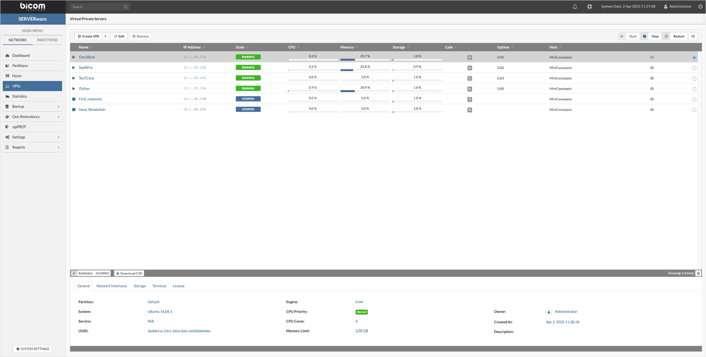
At the bottom of the interface, six tabs are available, each serving a specific function. These tabs are:
-
The General tab in the Details pane displays key information about an individual VPS, including its base template version, the partition it belongs to, the owner's name, and the details of its allocated resources.
-
The Network Interfaces tab displays information about the logical subnets to which the VPS is connected.
-
The Storage tab provides details about a VPS's storage volume, including its location, size, storage protocol, allocated bandwidth, and IOPS limit. Within this tab, users can adjust storage settings—such as increasing or reducing the assigned size—or change the storage protocol.
-
The Snapshots section allows users to create snapshots of a VPS, providing a restore point that can be reverted to in case of issues. Users can also clone a VPS from a selected snapshot or manage existing snapshots, including deleting them when no longer needed.
-
The Terminal tab allows users to open a TTY session for the selected VPS directly within the interface. It offers a faster alternative to SSH by providing console access in the same tab, keeping everything in one place.
-
The License section allows users to view the active license for a VPS and, if needed, reload the license for that specific VPS.
¶ Creating Virtual Private Server
To make it quick and easy to create a new virtual server, SERVERware provides virtual server templates. A template is a pre-configured virtual server with specific settings and configurations. When a new virtual server is created from a template, it inherits these configurations and settings. Templates are helpful for efficiently creating multiple identical virtual servers. By default, virtual servers created from templates use thin provisioning. This means that all virtual servers based on a template share the same base image as the template, saving storage space.
For instructions on how to download a template, please refer to the Templates section.
There are three types of templates in SERVERware:
- OFFICIAL
- COMMUNITY
- OCI
Besides that, VPSs created from OFFICIAL templates are supported by two engines:
- LXC
- KVM (supported from SERVERware version 4.5.0 and above)
NOTE: Please note that VPSs created from COMMUNITY and OCI templates are created as KVM for security reasons.
LXC (Linux Containers) is a lightweight virtualization technology that provides an efficient and secure way to run multiple isolated Linux systems on a single host. With LXC, each container runs its own isolated user space, but all containers use the host machine's Linux kernel. This allows for better performance compared to full virtualization, as containers are not fully emulated like virtual machines. SERVERware's implementation of LXC allows running Linux containers, including PBXware or Docker containers, fetched as OCI images from Docker Hub and similar repositories. This makes it easy to deploy and manage various services using open standards and tools.
KVM stands for Kernel-based Virtual Machine and is based on Firecracker, an open source virtualization technology that is purposely built for creating and managing secure, multi-tenant container services. With KVM, each VPS has a fully emulated or virtualized machine to run its copy of the Linux kernel, providing better isolation at the cost of some additional performance. From a security standpoint, this is a much better approach to partitioning resources between multiple services and their users. SERVERware's implementation of KVM can run unmodified Linux containers as VPSs which can either be PBXware or Docker containers fetched as OCI images from Docker Hub and similar sources. Additionally, one can pack and distribute service software using open standards and tools.
Create New VPS
Follow this procedure to create a new virtual server:
From the main navigation bar, open the VPS section to access the main VPS page. This view provides access to VPS details and actions such as creating, cloning, removing, starting, stopping, or pausing a VPS.
To begin the creation process, click the Create VPS button at the top of the page. A dialog window will open, prompting for the necessary information to set up the new virtual server.
The Create VPS dialog is organized into several tabs, each becoming available only after the previous one has been successfully completed. This step-by-step flow ensures that all required information is entered in the correct order. Once a tab is filled out, it remains accessible—allowing users to go back and review or modify previous steps at any time without restrictions.
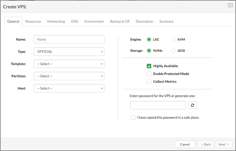
¶ General
The General tab is where all key configuration settings for the new VPS are defined. This is the first step and must be completed before moving on to the next tabs:
-
Name: Enter a clear and descriptive name for the VPS to help with easy identification later.
-
Type: Select the type of VPS you want to deploy, depending on the intended use (e.g., PBXware, custom OS).
-
Template: Choose a template from the available list. The selected template will serve as the base system for the VPS.
-
Partition: Select the storage partition where the VPS will reside.
-
Host: Choose the host that will run the VPS.
-
Engine: Pick the virtualization engine that will power the VPS.
-
Storage: Select between NVMe or iSCSI protocols. These options are configured in the VPS's Storage tab.
-
Highly Available: When enabled, the VPS is set up with high availability, allowing failover to another host.
-
Enable Protected Mode: When enabled, only administrators can start, stop, or restart the VPS. Useful for preventing unintended actions.
-
Collect Metrics: The Collect Metrics option enables the collection of performance and usage metrics for a specific VPS. Once enabled, these metrics can be reviewed manually through the terminal or automatically visualized using the Grafana tool.
-
Password Field: Manually enter a password for the VPS. For security, existing passwords won't be shown. The password must be at least 8 characters long.
-
Generate Password: Click to have SERVERware automatically generate a strong password that meets security best practices.
-
Confirmation Checkbox: Must be checked to confirm that the password has been copied and stored securely. This ensures the password isn't lost after VPS creation.
Once all required fields in the General tab are completed, click Next to proceed to the Resources tab and configure the VPS resource allocation.
¶ Resources
The Resources tab is used to define the performance and capacity settings for the VPS.
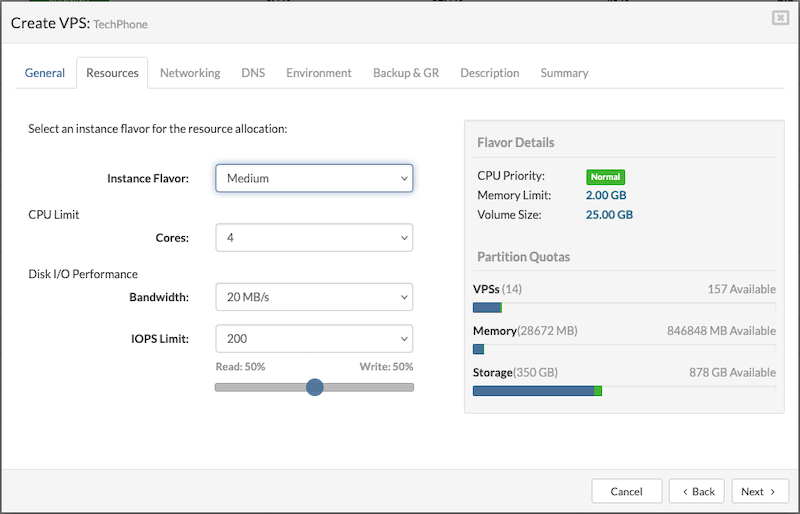
Instance Flavor
Select a flavor from the list that offers a resource allocation suitable for the VPS requirements.
By default, there are six instance flavor templates. However, users can create custom flavors in System Settings > Instance Flavors. Custom flavors, along with any other flavors, can be enabled or disabled by navigating to the Partitions section. Select the desired partition, open the Edit option, and navigate to the last tab, which manages Instance Flavors. From there, users can enable or disable specific flavors as needed.
CPU Limit
This field allows users to set a limit on the number of CPU cores allocated per VPS. The available options include:
- Number of cores: 1, 2, 4, 6, 8, 10, 12, 14, 16, 18, 20, 24, 28, 32, 64
- Unlimited (no restriction on CPU cores)
The default values for CPU limits are inherited from the selected resource flavor.
Disk I/O Performance
- Bandwith: Controls how fast the VPS can read and write data to disk (measured in MB/s).
- IOPS Limit: Limits how many read/write operations the VPS can perform per second. The default is 150, with options to set it to:
- • 100
- • 200
- • 500
- • 1000
- • Unlimited (no limit on disk operations)
The default values for Read/Write IOPS limits are inherited from the selected resource flavor.
PBXware RAM Disks
- AstDB RAM Disk: This sets the size of the RAM disk used to store the Asterisk database. This option applies only to PBXware-based VPSs and should only be adjusted if there are performance issues.
- Call Recordings RAM Disk: This sets the size of the RAM disk used to store call recordings. (Applicable to PBXware only)
Mount points
Assign the size of the mounted folder on /tmp for VPS.
Temporary Directory Size:
- Default value for all VPSs will be 256MB
- Minimum value is 64MB
NOTE: It is not recommended to set the temp directory size to more than 50% of the VPS's total RAM.
Assign the size of the mounted folder on /run for VPS.
• Size of run directory:
- Default value for all VPSs will be 128MB
- Minimum value is 64MB
Run directory size larger than 25% of RAM given to VPS is not recommended.
Once all resource settings are configured, proceed by clicking the Next button to set up VPS networking in the Networking tab.
¶ Networking
In the Networking tab, choose a logical subnet from the dropdown to connect the VPS. A VPS can be connected to multiple subnets, with a maximum of five.
Before adding additional subnets, ensure the required network is created under Settings > Networking. After the network is created, it must be assigned to the partition where the VPS will run. To assign a network to a partition, go to the Partitions section, select the partition, click Edit, and in the Networking tab, add the desired network.
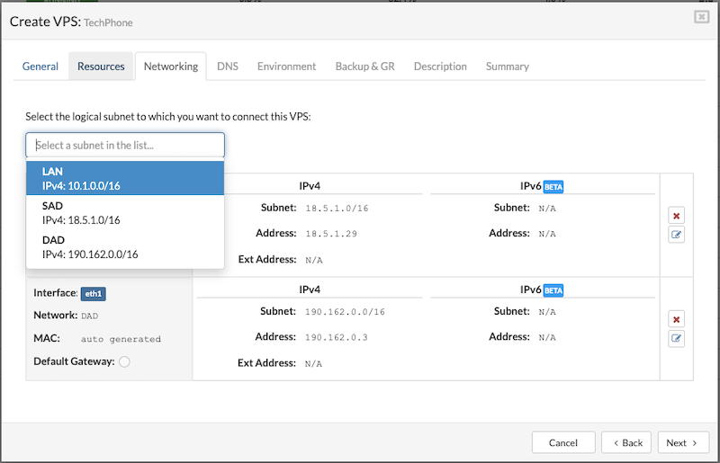
To proceed with creating the VPS, users must fill in the following details:
- Address: Enter an IPv4 address from the selected logical subnet. (The available IP addresses for use will be predefined for the chosen subnet.)
- External Address: Enter a public IP address (optional).
- MAC: Enter the MAC address manually, or leave the field blank to have one auto-generated.(optional)
- Default Gateway: Select this option if you want the subnet to act as the default gateway for the VPS. This is useful when multiple network interfaces are added.
- If the selected subnet has IPv6 enabled, users can also enter an IPv6 address for the VPS.
To add multiple subnets to a VPS, select a subnet from the dropdown menu, then click the Save button on the right side of the active window. Once saved, the option to add another subnet becomes available. Subnets can also be removed from the list at any time by clicking the X button next to the corresponding entry.
Once the subnet list is configured, click the Next button to proceed to the DNS Zone setup.
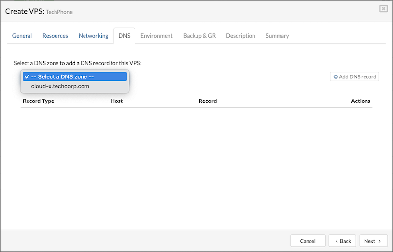
¶ DNS Zone
A DNS zone defines how network services and domains are resolved within SERVERware. To add a DNS zone to a VPS, it must first be configured under Settings > Networking > DNS. The supported record types in SERVERware are SRV and CNAME
¶ DNS SRV
The DNS lookup process first checks for SRV records. Proper use of SRV records allows administrators to distribute a service across multiple hosts within a partition, move the service between hosts without interruption, and designate certain hosts as primary and others as backups.
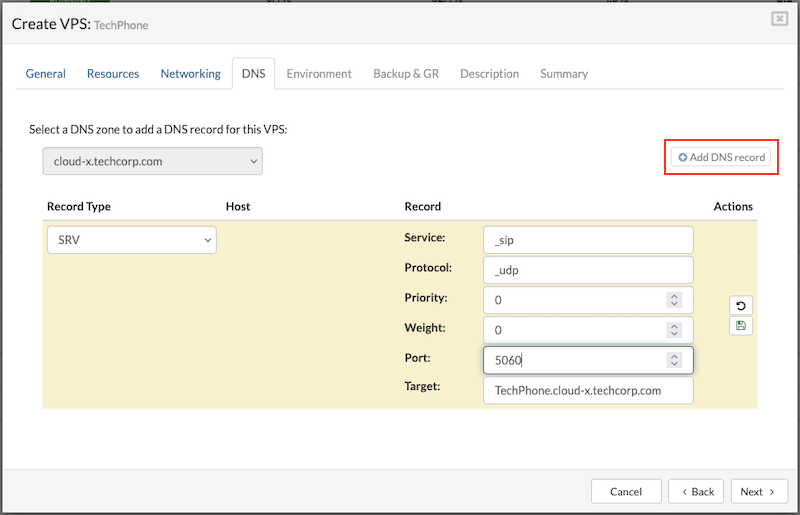
To configure a DNS SRV record for the VPS, fill in the required fields and click Save to apply the settings.
-
Service
The symbolic name of the service. For example, the service name used for IP telephony is "_sip" or "_sips" for TLS. -
Protocol
The protocol used to access the service. SIP clients can use either "_tcp" or "_udp," depending on the client configuration. TLS only works with "_tcp." -
Target
The partition name associated with the resource record. Enter the full path to the PBXware VPS, including the VPS name, e.g., "vpsname.cluster1.serverware.xyz." -
Priority
The priority of the service. Servers are ordered by priority, with lower numbers having higher priority. If priority order isn't needed, set it to 0. -
Weight
Used for load balancing within the same priority. A higher weight means the server can handle more requests. Servers with higher weights are more likely to appear earlier in the list. Set the weight to 0 if load balancing isn't needed. For all weights within the same priority, use nonzero values to indicate the relative load each server can handle. (An SRV record with weight 0 will have a lower probability of appearing earlier than those with nonzero weights.) -
Port
The port number assigned to the SIP service, typically "5060" or "5061" for TLS. While it's generally recommended to use a single SRV record for each SIP server, some implementations may require multiple SRV records with a separate service record for each resource name, especially when some clients use "TCP" and others use "UDP" for the same service.
EXAMPLE
A VoIP provider, TechVoice, hosts a SIP-based PBX system that multiple companies use for VoIP services. The main PBX system is located at: pbx.techvoice.com. Two client companies, SwiftPro and OmniByte, need to configure their VoIP clients (like softphones or desk phones) to connect to the PBX system automatically. Instead of manually entering IP addresses and ports, they use DNS SRV records to define where SIP services are available.
Each company sets up SRV records so their VoIP clients automatically find and connect to the correct SIP server.
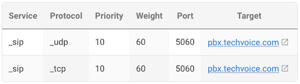
This means SwiftPro's VoIP clients will first try connecting via UDP on port 5060 because it has the highest priority (10). If UDP is unavailable, they will fall back to TCP on port 5060, which has a lower priority (20).
How This Works in Practice?
- A SwiftPro employee sets up a softphone and enters only swiftpro.com as the SIP domain.
- The VoIP client automatically queries the DNS for SRV records related to _sip._udp.swiftpro.com or _sip._tcp.swiftpro.com.
- The DNS responds with the correct server address, port, and protocol (pbx.techvoice.com on port 5060).
- The softphone connects seamlessly, without the user needing to enter technical details.
¶ DNS CNAME
The DNS lookup routine checks for CNAME (Canonical Name) records to resolve domain aliases. Proper use of CNAME records allows administrators to map multiple domain names to a single canonical domain name. This simplifies domain management, enables flexible redirection of services to different hosts without changing multiple DNS entries, and ensures consistency by centralizing the resolution to a single target domain.
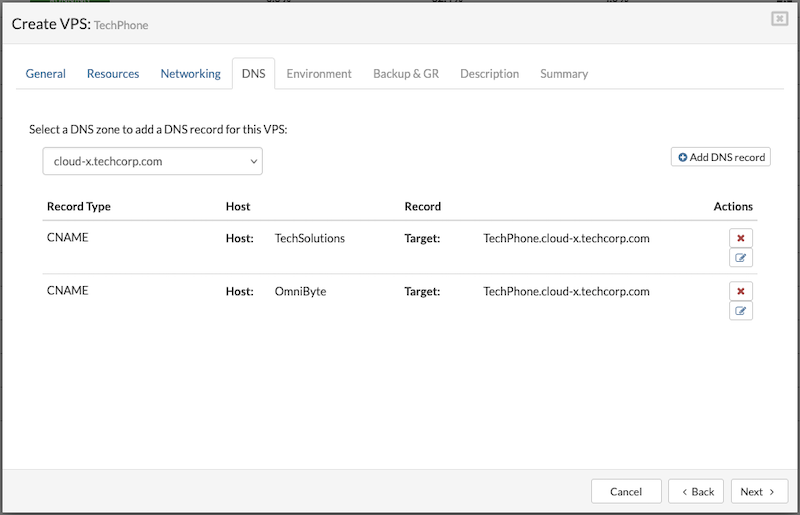
Multiple CNAME records can be created to link two or more different domain aliases to a single VPS. To create a CNAME record, users need to provide the following information:
-
Host: Enter the custom domain or subdomain to be used as an alias for the VPS (e.g., TechSolutions or OmniByte).
-
Target: Enter the main domain name (canonical name) that the alias will point to, such as pbx.techsolutionspany.zone1.primary. This is the actual domain of the multi-tenant PBXware instance.
This setup lets multiple domain aliases point to the same PBX service without exposing its IP address. It also makes DNS management easier, since changes can be made by updating DNS records without modifying the VPS settings.
EXAMPLE
A VoIP service provider, TechVoice, hosts a PBX system on their server with the domain name: pbx.techvoice.com. Two client companies, SwiftPro and OmniByte, want to use their own branded subdomains to access the PBX system while keeping TechVoice's infrastructure hidden. Instead of setting up separate servers, TechVoice creates CNAME records that point these subdomains to their actual PBX system:
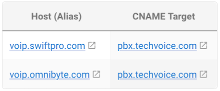
How This Works in Practice?
- When SwiftPro employees enter voip.swiftpro.com in their VoIP client, the DNS resolves it to pbx.techvoice.com.
- When OmniByte employees enter voip.omnibyte.com, it also resolves to pbx.techvoice.com.
- The A record for pbx.techvoice.com points to the actual IP address of the PBX system, allowing users to connect seamlessly.
To continue with the process of creating VPS, save the settings and start the VPS.
¶ Environment
In SERVERware, external environment variables needed for certain VPS types to work correctly can be added. These variables are available in the Docker Hub for the chosen image.
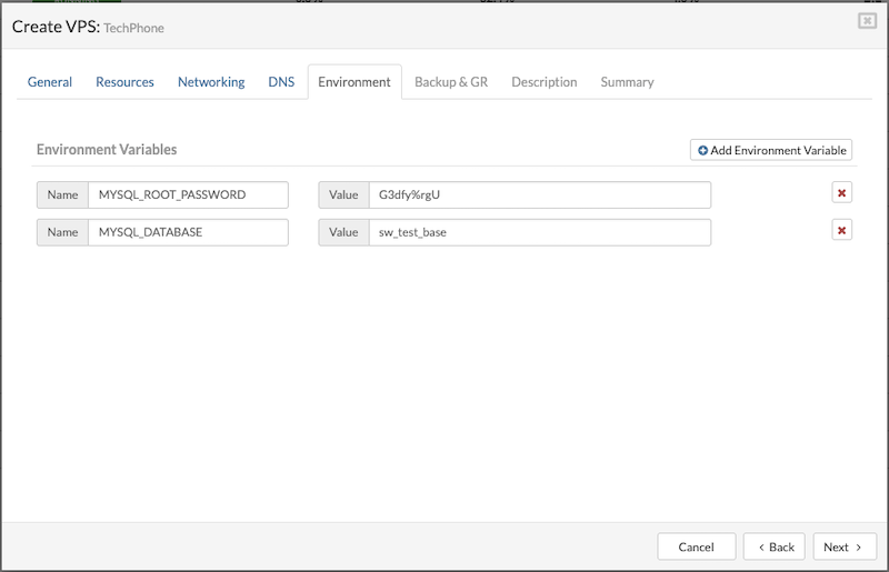
¶ Backup & GR
The Backup & GR tab lets users manage backup and replication settings for the VPS:
Exclude from Backup: Check this option to prevent the VPS from being included in backup processes.
Include in Replication: When enabled, a dropdown menu appears listing available replication cycles. Select the desired replication cycle to include the VPS in replication.
¶ Description
This tab allows users to add and view important notes or details related to the VPS. It's a place to document the VPS's purpose, special settings, or any other relevant information that helps with identification and management.
¶ Summary
The summary provides a quick overview of the key configuration and resource details for a VPS. It includes information such as the VPS name, hosting details, selected template, storage and networking settings, resource allocations like memory and disk size, and availability options.
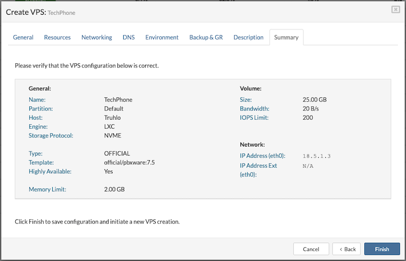
¶ Create VPS from OCI
Creating a VPS from an OCI image allows quick deployment of containerized applications using standardized software packages. By selecting an OCI image, SERVERware automatically sets up the necessary environment to run the container, simplifying the process of launching virtual servers with pre-configured software. This method offers flexibility and ease when deploying third-party or custom applications within the VPS.
Before creating a VPS from an OCI image, certain steps need to be completed first:
- Add the OCI registry in Templates > OCI Registries.
- Download the OCI Runner template from Templates > Community Templates.
These steps are required before creating a VPS from an OCI image to ensure proper access and deployment.
Create OCI VPS
To create a VPS from an OCI image, follow these steps:
- Navigate to the VPS menu and click Create New VPS at the top.
- In the popup window, go to the General tab and select the OCI option to use OCI templates for the VPS.
- Choose the oci-runner template from the dropdown menu.
- Select the desired Partition.
- Choose the Host where the VPS will run.
- Pick the appropriate Registry.
- Enter the OCI image name (e.g., library/mysql) and specify the tag (e.g., latest).
The rest of the VPS creation process is the same as with other types and is quite straightforward.
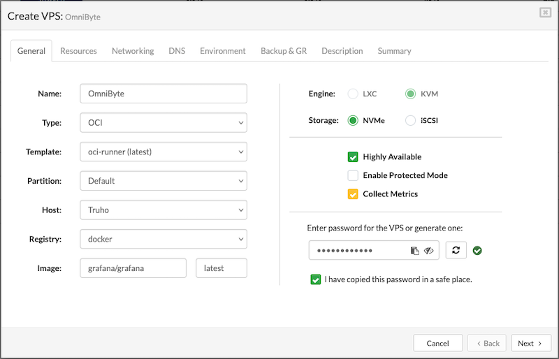
Starting with SERVERware 4.7, volume mapping for OCI images is supported directly through the GUI. This feature lets users link folders or files from the host machine to specific directories inside a container. SERVERware's volume mapping is tailored for VPS instances and the Docker containers running within them, making data sharing and persistence simple and efficient.
¶ Managing Virtual Private Servers
Managing Virtual Private Servers (VPS) involves various administrative tasks to ensure optimal performance, resource allocation, and flexibility. Administrators can start, stop, and restart virtual servers as needed, modify ownership, and adjust storage capacity. SERVERware allows for changes between VPS engines (LXC or KVM), as well as cloning and migrating instances for scalability or maintenance. Additionally, restoring virtual servers, reclaiming free space using TRIM, and shrinking VPS instances help optimize resource usage. VPS snapshots provide a reliable way to create restore points, ensuring data protection and quick recovery when needed.
¶ Editing VPSs
Details of a virtual server, such as its name or memory size, can be edited. However, changing the template or the partition the virtual server belongs to is not allowed. Additionally, the VPS engine can only be changed when the VPS is stopped. Changes to the VPS network configuration will take effect only after the virtual server is stopped and restarted.
To edit VPS details, follow these steps:
- In the Virtual Private Servers view, select the VPS to be edited.
- If the VPS is not visible in the list, use the search function to locate it.
- Click the Edit button to open the Edit VPS dialog, where fields that cannot be changed are disabled.
- Modify the desired details in the enabled fields under the appropriate tabs.
- Click Save to update the VPS details in the view.
Editing a VPS can be done in two ways: while the VPS is running, which allows only a limited set of options to be changed, and when the VPS is stopped, which provides access to a wider range of configuration options.
¶ Starting, Stopping and Restarting VPSs
Management actions such as VPS starting, stopping, and restart is performed directly on the virtual server by using dedicated buttons for that purpose located on the top-right of the virtual server list.
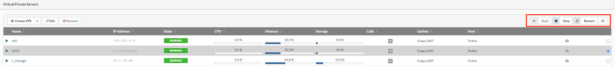
To perform an action, select the desired VPS and click the Start, Stop, or Restart button as needed.
¶ Changing VPS Ownership
To change the owner of a VPS, follow these steps:
- In the Virtual Private Servers view, select the VPS whose ownership needs to be changed.
- If the VPS is not visible in the list, use the search function to find it.
- Click the Change Owner button.
- In the Change Owner dialog, select the new owner from the list.
- Click Change to update the VPS ownership.
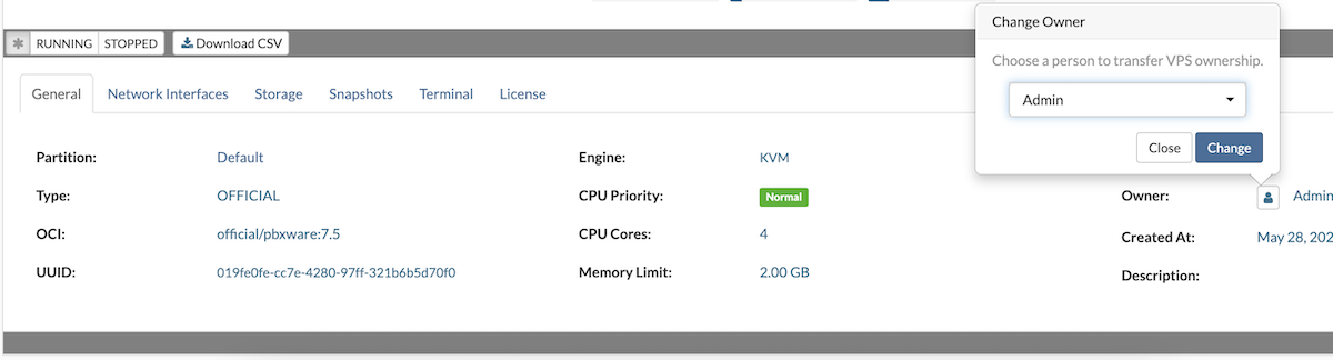
¶ Increasing VPS Storage
To increase the storage space of a VPS, follow these steps:
- In the Virtual Private Servers view, locate and select the VPS that requires additional storage.
- If the VPS is not visible in the list, use the search function to find it quickly.
- Navigate to the Storage tab within the VPS details.
- Click the Extend Volume button to begin the storage expansion process.
- Specify the new desired storage size as prompted, then confirm the change.
- The system will resize the VPS storage volume accordingly, increasing the available space.
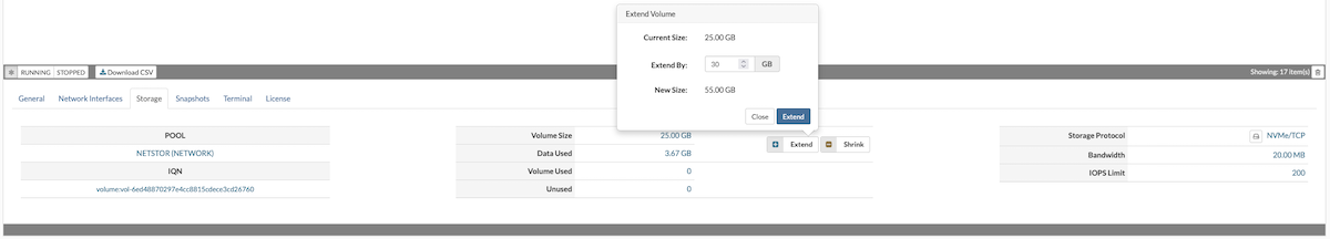
Note: The VPS must be stopped before increasing its storage space.
¶ Storage Protocols
Within the VPS Storage tab, users can choose between two storage protocols: NVMe and iSCSI.
NVMe (Non-Volatile Memory Express) is a fast, high-performance storage protocol designed to work with modern SSDs, providing low latency and high speed for data transfer. It's ideal for applications that need quick access to storage, offering better performance compared to traditional storage methods.
iSCSI (Internet Small Computer Systems Interface) allows storage devices to be connected over a network using standard IP protocols. It's more flexible for remote storage setups and can be used in environments where storage is shared across multiple servers.
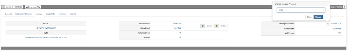
Generally, NVMe is preferred for its speed and performance when storage is local, while iSCSI is a good choice for remote or shared storage environments. Users can switch between these protocols based on their VPS storage needs and infrastructure setup.
Note: The VPS must be stopped before changing its storage protocol.
¶ Reclaim Free Space - TRIM
To reclaim free storage space on a VPS (VPS must be stopped), follow these steps:
- In the Virtual Private Servers view, select the VPS that requires free space reclamation.
- If the VPS is not visible in the list, perform a search and ensure the VPS is stopped.
- Go to the Storage tab and click the Trim button.
- When the Trim storage dialog appears, click YES to begin the trimming process.
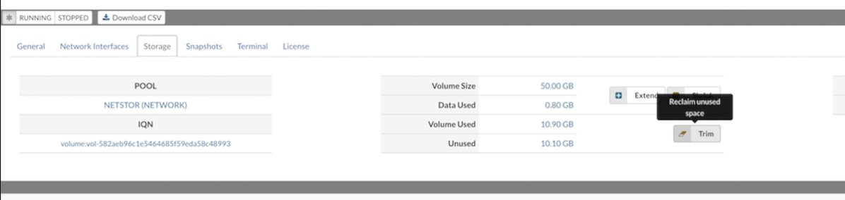
The Trim feature becomes available only when there is more than 10% of unused space that can be reclaimed.
¶ VPS Shrink
In SERVERware 4.7, shrinking VPSs can be done with a single click through the SERVERware GUI. SERVERware will automatically calculate the required volume size based on the Data Used values within the volume.
Before shrinking the volume, the VPS needs to be stopped.
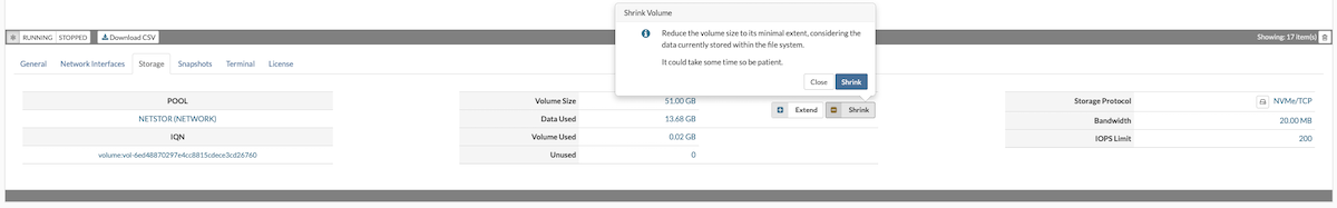
The shrink button is located next to the extend button and as with the extend functionality, this is a process that might take a while, so it's recommended not to immediately start the VPS once the dialog is closed. The shrinking process can be tracked through the system logs and audit logs.
¶ VPS Snapshots
A snapshot is a read-only copy of a dataset or volume, created almost instantly without consuming additional storage space at the moment of creation.
In SERVERware, snapshots can be taken for individual VPS instances and managed through the Snapshots tab. Supported actions include creating a new snapshot, deleting individual snapshots, removing all snapshots associated with a specific VPS, and rolling back the VPS to the state captured at the time the snapshot was created.
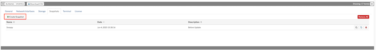
To create a snapshot, click the Create Snapshot button and enter a name along with an optional description to help identify it later.
All snapshots associated with a specific VPS are listed under the Snapshots tab, where they can be managed by SERVERware administrators.
¶ Removing Snapshots
Snapshots can be deleted individually or all at once by using the Delete All button. In SERVERware, creating or removing snapshots—whether individually or in bulk—does not require stopping the VPS.
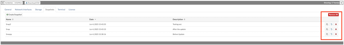
One of the main advantages of snapshots is that they allow for the entire dataset to be rolled back to the point in time when the snapshot was created, which can be useful in many scenarios, for example, upgrades, various maintenance tasks, to pull out certain files and more.
¶ Rollback from Snapshot
To perform a rollback of a SERVERware snapshot, simply click on the Rollback button. In order to complete the rollback function, the VPS needs to be stopped. When performing a rollback to a specific snapshot, all snapshots created after the rollback point will be automatically removed.
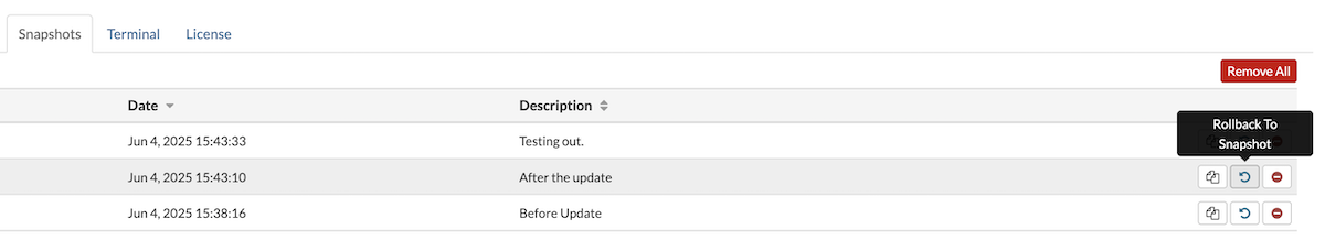
Snapshots initially do not take up any storage space, however once more data is added to the original dataset, so will the snapshot increase in size which is why it's recommended practice not to store snapshots for longer periods of time.
Snapshots in SERVERware will be automatically removed after 15 days.
¶ Open TTY session on VPS
TTY provides passwordless CLI access to a VPS directly from the SERVERware GUI. It is useful when SSH access is unavailable due to misconfiguration, custom templates without an SSH client, or other issues. Since TTY is an internal SERVERware service, it operates independently of the VPS's status, ensuring reliable access for troubleshooting and maintenance.
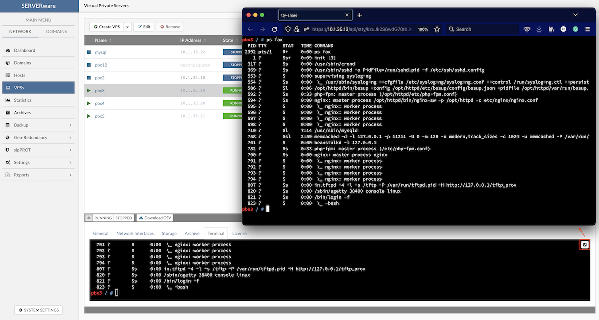
Multiple TTY sessions can be opened for a single VPS directly from the SERVERware GUI.
- Closing the browser tab does not end the session.
- This functionality is restricted to SERVERware administrators; partition administrators and VPS owners do not have access.
- TTY session links (URLs) are non-shareable.
- Sessions remain functional even if the VPS lacks a defined network interface.
- All active TTY sessions are automatically closed when the VPS is stopped.
- A TTY session will time out after 30 minutes of inactivity.
We strongly advise you to use some kind of screening tool for performing actions that can take longer than 30 min (tmux, screen, etc..)
Start TTY Session:
To access the VPS console via TTY:
- Create a new VPS using either a SERVERware or OCI template.
- Start the VPS.
- In the bottom information panel, navigate to the Terminal tab.
- Click the Open TTY button to launch console access for the VPS.
- Use the TTY console to perform various tasks within the VPS environment.
¶ Moving VPSs
¶ Moving VPS to Another Partition
A stopped VPS can be moved to another partition within the SERVERware network. This is particularly useful for balancing resource usage or preparing for server maintenance. Live VPS migration is not yet supported, but while a VPS is stopped, it can be relocated as needed.
Follow this procedure to move VPS to another partition:
- In the Virtual Private Servers view, select the VPS that you want to move.
- If the VPS that you want to move is not visible in the list, perform a search.
- Locate the Create VPS dropdown menu and select the Move VPS option.
- The Move VPS dialog appears.
- Select a partition and click the Move button to initiate move operation.
- Monitor task progress in the VPS view. The partition column should show a new name for the moved VPS.
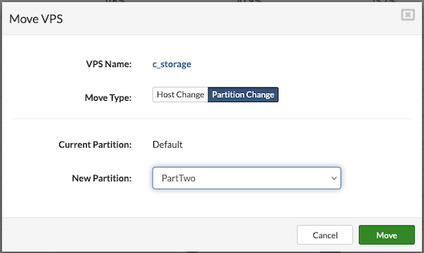
¶ Moving VPS to Another Host
Follow this procedure to move VPS to another host:
- In the Virtual Private Servers view, select the VPS that you want to move.
- If the VPS that you want to move is not visible in the list, perform a search.
- Locate the Create VPS dropdown menu and select the Move VPS option.
- The Move VPS dialog appears.
- Select new host and click the Move button to initiate move operation.
- Monitor task progress in the VPS view. The host column should show a new name for the moved VPS.
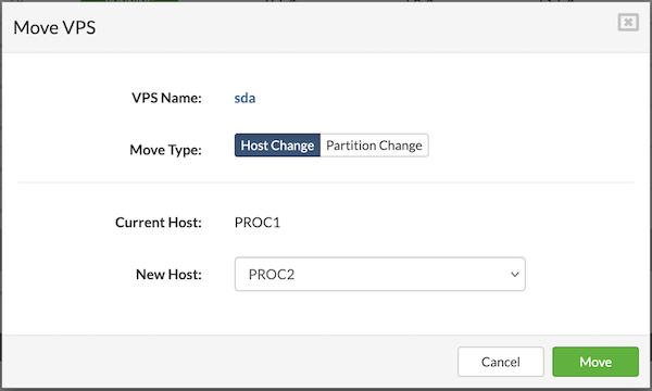
¶ Cloning VPSs
In SERVERware, VPS instances can be cloned whether they are running or stopped. This is particularly useful for duplicating fully configured and operational VPS setups.
To clone a VPS:
- In the Virtual Private Servers view, select the VPS to be cloned.
- If the VPS is not immediately visible, use the search function.
- Click the Clone VPS button.
- The Clone VPS dialog will appear to proceed with the cloning process.
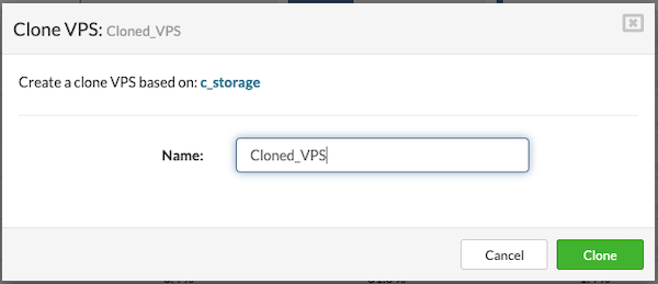
- Enter a new name for a VPS and click the Clone button.
- Monitor task progress in the VPS view. The name column should show a new name for the cloned VPS.
¶ Removing VPSs
Follow this procedure to remove a VPS:
- In the VPSs view, select VPS that needs to be removed.
- Click the Remove button. A confirmation dialog appears.
- Click Yes. VPS disappears from the list.
When a VPS is deleted or removed by a user, it is removed from both the storage host and the main SERVERware interface. However, these deleted VPSs are not permanently lost—they are moved to a special area called Removed VPSs, which functions like a recycle bin.
A VPS can only be removed when it is in a stopped state.
There are two possible scenarios:
If no backup is configured: The removed VPSs cannot be restored. They will appear in the Removed VPSs list only as part of the management history and cannot be recovered. These entries are visible solely for tracking and audit purposes.
If a backup is configured on the SERVERware system: The Removed VPSs list allows users to restore VPSs that were deleted accidentally or intentionally. This recovery feature is only available if a backup has been previously configured. For detailed information on setting up and managing backups, refer to the Backup section of this document.
¶ Restore VPSs from the Removed VPSs List
To restore the removed VPS, follow these steps:
-
Go to the VPS menu and click on the Removed VPSs icon.

-
Select the VPS and click Restore
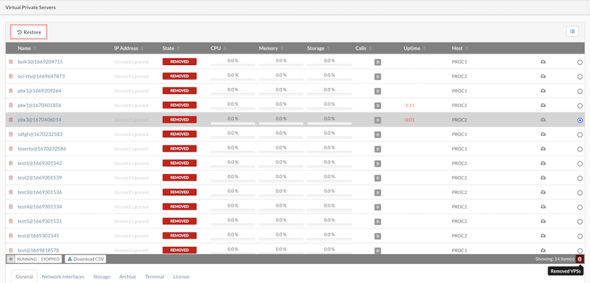
-
Pop-up menu will appear, then select Restore Point, Partition, Host, and Name of the VPS.
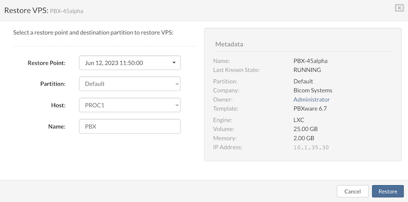
- Click the Restore button to start the restore VPS process.
Removed VPS will be automatically removed from SERVERware inventory once their latest backup expires.
¶ Statistics
SERVERware Statistics is a built-in monitoring tool designed to provide administrators with insights into the performance and resource utilization of the SERVERware environment. It gathers data on various metrics, including CPU usage, memory consumption, disk I/O, and call activity, for both Hosts and VPSs.
Key Features and Uses
-
Resource Monitoring: Track CPU, memory, and disk I/O usage over time to identify trends and potential bottlenecks.
-
Call Activity Tracking: Monitor the number of calls made across all VPSs, aiding in capacity planning and ensuring optimal performance.
-
Meeting Statistics: For environments utilizing conferencing features, statistics on active meetings, participants, and data transmission (sent/received) are available.
-
Storage Utilization: Assess storage usage, including logical and actual space used, to manage storage resources effectively.
SERVERware Statistics allows administrators to view data over various timeframes, such as hourly, daily, or weekly intervals. This temporal analysis facilitates the identification of patterns, peak usage periods, and potential issues before they impact system performance.
To access SERVERware Statistics, administrators need to log in to the Web Control Panel and go to the "Statistics" section, where they can view comprehensive resource usage data for Hosts and VPSs.
¶ Host/VPS Performance Charts
The Statistics section provides a visual overview of system performance through interactive charts. It includes a settings panel for selecting metrics and a chart display area for viewing the data. Users can monitor performance metrics for both Hosts and VPSs, as well as perform side-by-side comparisons between multiple VPSs. The available metrics in the settings panel include:
- CPU Usage (Utilization/IO Wait): Measures the percentage of CPU actively processing tasks and the time spent waiting for input/output operations.
- CPU Load: Indicates the overall demand on the CPU, showing how many processes are competing for CPU time.
- Memory Usage: Shows the amount of RAM currently in use by the system or VPS.
- Concurrent Calls: Tracks the number of simultaneous calls being handled.
- Pool Usage: Reflects the usage of resource pools allocated to VPSs.
- Network Bandwidth Utilization: Displays the amount of network data being sent and received.
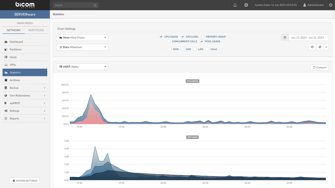
To view performance charts for Hosts or VPSs, start by opening the Statistics view. First, choose the category of charts to display—select either Host Chart to see data for the Host system, or VPS Charts to focus on individual VPS performance. Next, decide whether to display the Average or Maximum values for the data series, depending on the type of insight needed. Then, pick the specific metrics to include on the chart, such as CPU usage or memory consumption. Finally, select the time period over which the performance data should be displayed, allowing for analysis of recent or historical activity. This step-by-step process helps users customize the charts to get a clear and relevant picture of system performance.
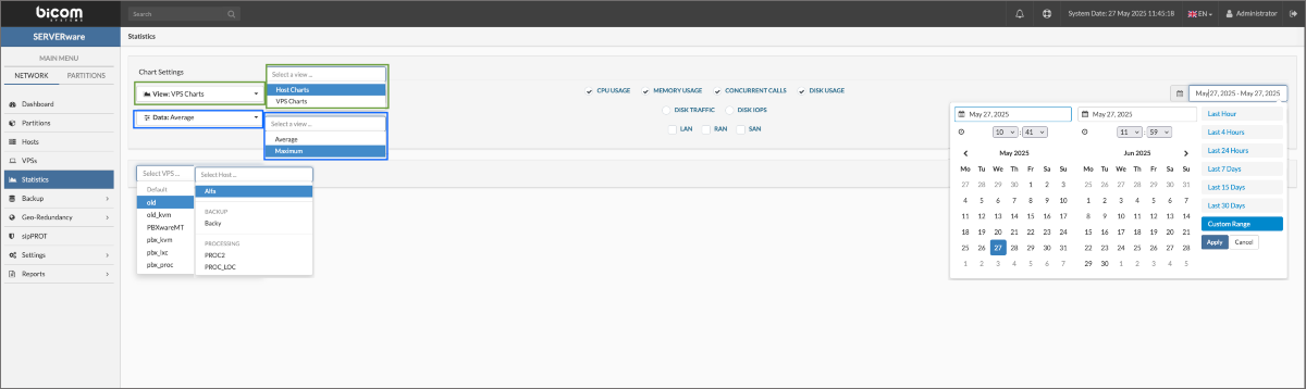
¶ Compare HOSTs/VPSs Statistics
Clicking the Compare button enables the comparison of performance data across multiple VPSs. This feature allows users to view side-by-side charts, making it easier to identify differences in resource usage and performance trends between VPS instances. It's a useful tool for spotting which VPSs are under heavier load or may require adjustments to optimize overall system efficiency.
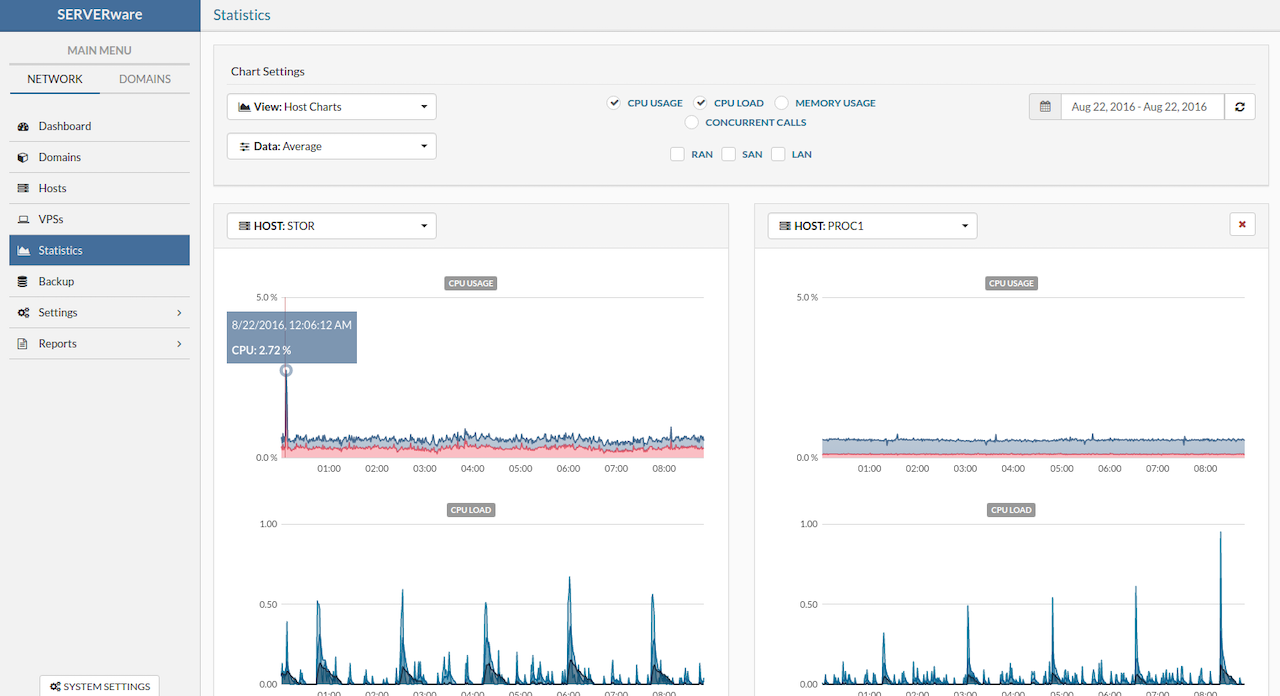
¶ Backup
The Backup feature in SERVERware is designed to safeguard Virtual Private Servers (VPSs) by creating regular backups, ensuring data integrity and facilitating recovery in case of system failures or data loss.
SERVERware's backup system allows administrators to schedule and manage backups of VPSs, capturing their current state and data. These backups can be stored locally or on a designated backup host, providing flexibility in backup strategies.
¶ Manage Backup Jobs
The Backup menu provides access to two key sections: Schedule and Browse & Restore.
The Schedule view displays a list of all configured backup jobs. When a specific job is selected, a history pane below shows the backup history for that job, including past executions and their status.
The Browse & Restore view allows users to navigate available backup hosts where backups are stored. After selecting a backup host and a corresponding backup set, a list of available VPS restore points is displayed in the pane below, making it easy to identify and restore from specific backups.
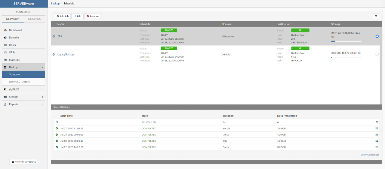
The following properties of a backup job are displayed on the Backup view as well as on the Add and Edit dialog boxes.
| Field | Description | |
|---|---|---|
| Name | The backup job name. Provide a descriptive name. | |
| Mode | Available choices for the backup Mode are Backup to ZFS and Backup to File (legacy) | |
| Partition | The name of the partition from which VPS backups will be created. It may be an individual partition or all partitions in the network. | |
| Destination | The name of a host dedicated to backup. It may be the existing Network Storage host, however, this is not recommended. | |
| Pool | The name of the backup dedicated pool. | |
¶ Schedule Backup Job
When setting up a new backup job in SERVERware, the configuration is divided into two main sections: General and Schedule.
In the General tab, begin by entering a Job Name—use a clear and descriptive title (e.g., Daily Backup) to easily identify the job later.
Next, select the Backup Mode—choose between Backup to ZFS or Backup to File (legacy). Backup to ZFS utilizes the ZFS file system's snapshot capabilities for efficient and reliable incremental backups, while Backup to File is the legacy method that stores backup data as traditional files.
Under Partition, choose a specific source partition to back up only the VPSs on that partition, or leave the default (All Partitions) selected to include all VPSs.
Then, specify the Destination host where the backups will be stored—ideally a dedicated server reserved for backup purposes. In the Pool field, define the file system location (path) or ZFS pool on the destination host where backups will be saved. The Dataset field is directly linked to the Pool field and automatically reflects the option selected in the Pool section.
In the Schedule tab, the Backup Type setting defines how backups are performed—either Full or Incremental. If Backup to ZFS is selected in the General tab, the backup type will be automatically set to Incremental and cannot be changed, as ZFS uses snapshot-based incremental backups by design. However, if Backup to File (legacy) is selected, users can choose between Full and Incremental backup types based on their preferences and requirements.
Set the At field to specify the time of day when the backup should run. Finally, use the Keep Backup option to define how long backups should be retained, selecting a retention period from the available options.
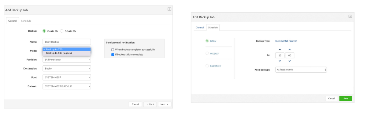
¶ Create Custom Dataset
SERVERware allows the creation of custom ZFS datasets for backup purposes by setting the srw:dstype property to backup. By default, SERVERware uses the SYSTEM-XXXX/BACKUP dataset for storing backups.
However, if a user wants to define a new dataset for backup storage, the following steps must be performed:
- Create a target directory (e.g., /newbackup):
~ # mkdir /newbackup - Create and configure the new ZFS dataset:
~ # zfs create SYSTEM-XXXX/newbackup -o mountpoint=/newbackup -o overlay=on -o compression=on -o srw:dstype=backup
Once created, the new dataset will appear as an available destination when configuring a backup job in the SERVERware Web Control Panel. This flexibility allows users to organize and separate backup storage across different datasets according to their needs.
¶ VPS Restore from Browse & Restore Menu
Restoring a VPS allows reverting it to a previously saved restore point. Using the Restore VPS option in the Browse & Restore menu will create a new copy of the VPS based on the selected backup.
To restore a VPS, follow these steps:
-
In the Backup menu, select the Browse & Restore submenu.
-
Select a Backup Host from dropdown and choose the backup host that contains the desired backup set.
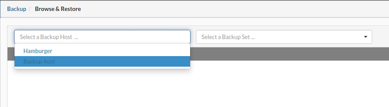
- From the Select a Backup Set menu, choose the backup set that contains restore points for the VPS to be restored.
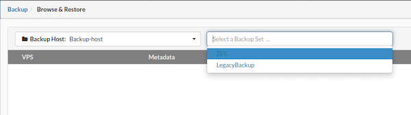
- Then, select the desired VPS and click the Restore button to initiate the restoration process.
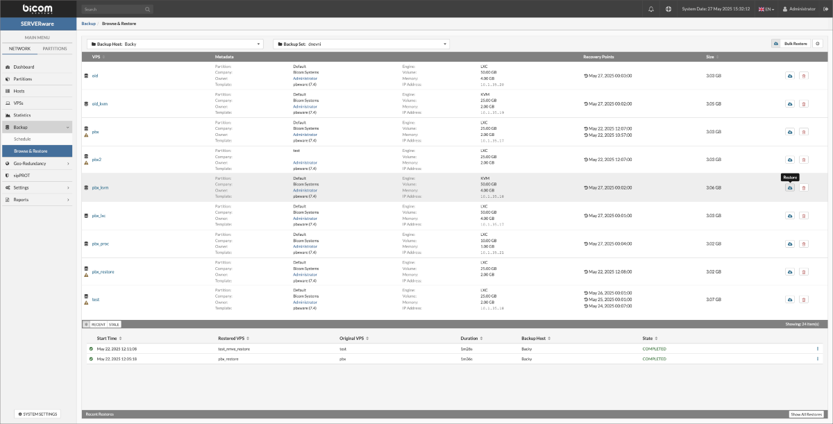
- Select a restore point and the destination partition for the VPS restoration, then click the Restore button to begin the process.
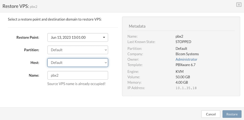
- A progress bar will display the restoration status as a percentage. If needed, the restore can be canceled at any time by clicking the red Cancel icon on the right. Canceling the restore will automatically delete the partially restored VPS and remove all related data from the process.
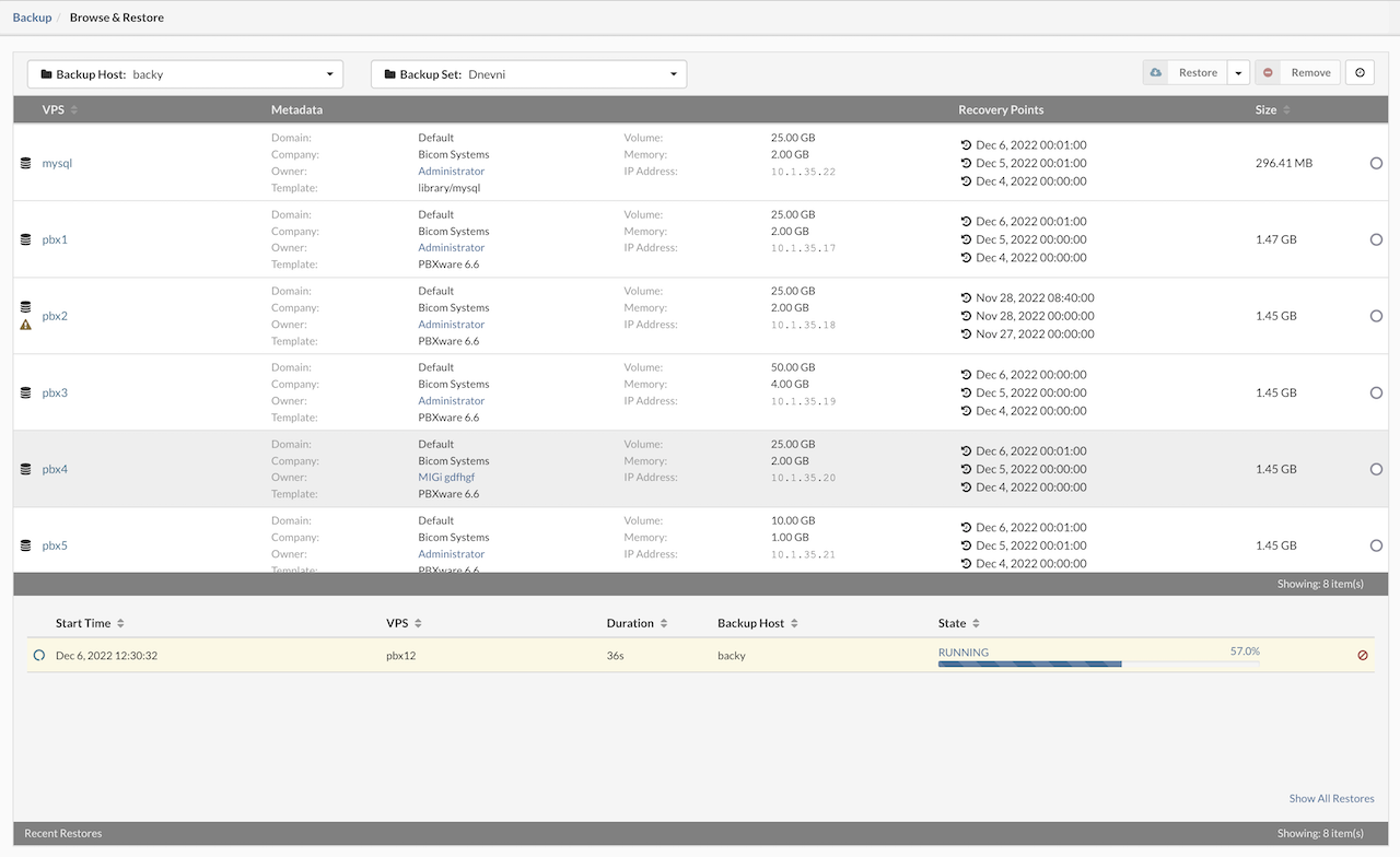
- Once the restoration is complete, the Recent Restores view will update accordingly, indicating that the restored VPS is ready for use.
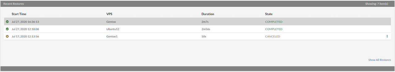
¶ VPS Bulk Restore from Browse & Restore Menu
The Bulk Restore feature in SERVERware enables administrators to efficiently restore multiple VPS instances from existing backup sets. This process creates new copies of the selected VPSs, each based on a chosen restore point.
Steps to Perform a Bulk Restore:
Navigate to the Backup menu and select the Browse & Restore submenu. From the Select a Backup Host dropdown, choose the host that contains the desired backup set.
In the Select a Backup Set dropdown, pick the backup set that includes the restore points for the VPSs intended for restoration.
Click on the Bulk Restore button located in the upper right corner of the interface.
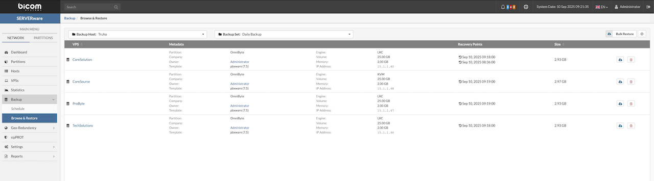
Configure Restoration Options for Each VPS:
-
Select the specific restore point.
-
Select the destination partition and host where the new VPS copy will be deployed.
-
Specify a name for the restored VPS, then add it to the restoration queue.
Once all desired VPSs are queued with their respective configurations, click the Start button to commence the bulk restore process.
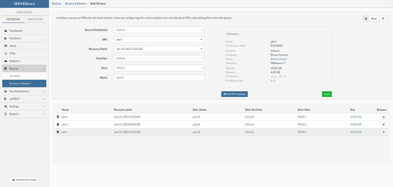
To view the status of the ongoing bulk restore task, return to the Browse & Restore submenu under the Backup menu, then select the backup host where the bulk restore job was initiated to view the progress and status of the ongoing restoration tasks.
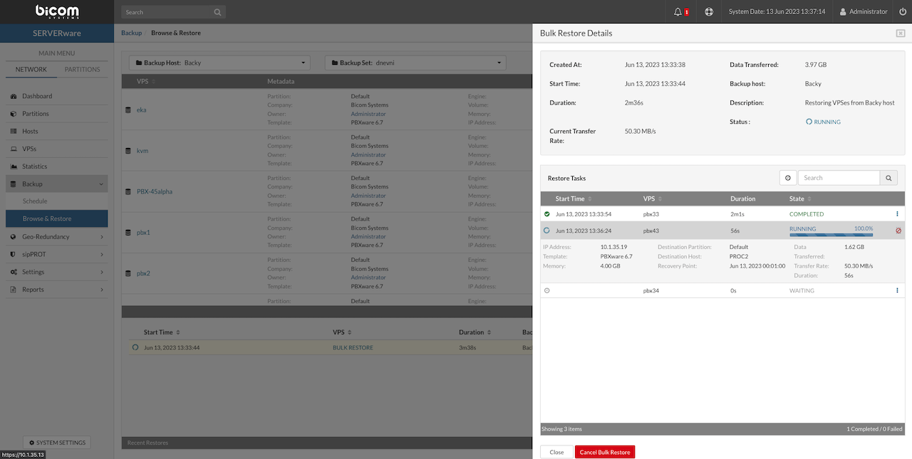
¶ Remove Backup Job
To remove a configured backup job in SERVERware, follow this process:
-
Navigate to the Backup section in the Web Interface.
-
Open the Schedule tab.
-
In the list of backup jobs, locate the job to be removed.
-
Click the Remove button located to the right of the Add Job button.
-
A confirmation dialog will appear. Confirm the removal by clicking Yes.
⚠️ Confirming this action will delete the backup job configuration and remove all associated backup sets stored on the backup server.
¶ Removing VPS from Backup
To prevent a specific VPS from being included in future backup jobs:
-
Open the VPS Section view and select the VPS to be excluded.
-
Click Edit to open the configuration dialog.
-
Navigate to the Backup & GR tab.
-
Enable the Exclude from Backup option.
-
Save the changes.
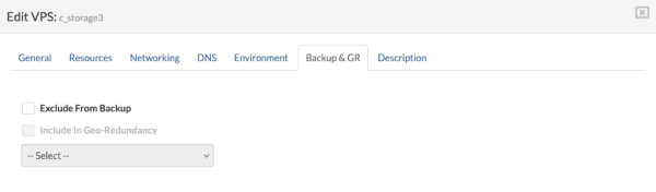
This setting ensures that the VPS will no longer be targeted by any backup jobs, even if a job is configured to include all VPSs on a partition.
¶ Geo-Redundancy
Geo-Redundancy in SERVERware is a strategic feature designed to enhance service availability, ensure business continuity, and provide robust disaster recovery capabilities. By replicating data and services across geographically dispersed sites, SERVERware minimizes downtime and safeguards against regional disruptions.
What is Geo-Redundancy?
Geo-Redundancy involves duplicating critical infrastructure components—such as Virtual Private Servers (VPSs) and PBXware instances—across multiple data centers in different geographical locations. In the event of a failure at the primary site, services can automatically or manually failover to a secondary location, ensuring uninterrupted operations.
How SERVERware Implements Geo-Redundancy
SERVERware's Geo-Redundancy feature operates through scheduled synchronization of data between primary and secondary sites. Administrators can configure replication intervals ranging from as frequent as every minute to once every 24 hours, depending on organizational needs. This flexibility allows for a balance between data currency and system performance. In scenarios where the primary cluster experiences a complete outage, the system facilitates the transfer of services to a geographically dispersed secondary site. This process ensures that VPSs and PBXware instances continue to operate with minimal disruption.
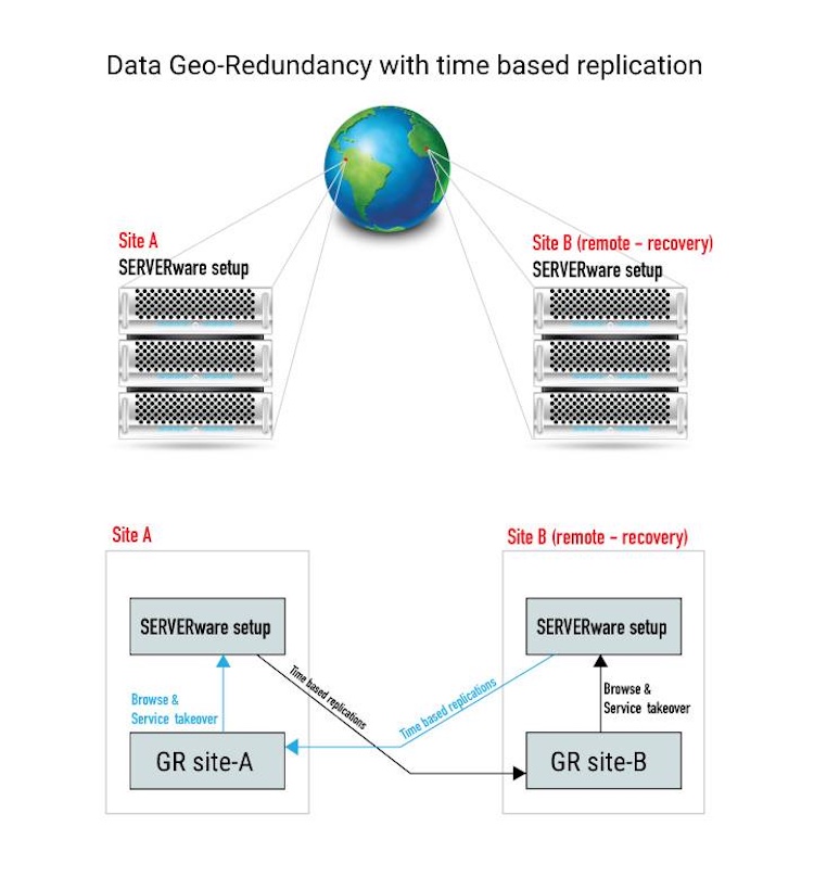
Benefits of SERVERware's Geo-Redundancy
-
Business Continuity: Maintains uninterrupted services during regional outages or disasters.
-
Disaster Recovery: Enables swift restoration of services by switching operations to a secondary site.
-
Scalability: Supports growth by allowing the addition of processing hosts and services across multiple locations.
-
Data Integrity: Ensures that data remains consistent and up-to-date across all sites through scheduled synchronization.
-
Operational Efficiency: Reduces downtime and manual intervention during failover processes.
¶ Key Capabilities Overview
¶ Replication and Recovery
Replication is done incrementally, meaning only the changes get transferred, which saves on bandwidth and storage. Users can set how often replication happens—every minute if needed—and choose which VPSs and partitions are included. It's also possible to keep several recovery points, so if one has unwanted changes, it's easy to roll back to an earlier state. There's also support for setting an alternate IP if the restored VPS will be running in a different network setup.
¶ Takeover and Failover
If a disaster hits, a VPS can be restored manually from any saved point in time. The process involves picking the VPS, choosing which recovery point to use, and setting the destination host and partition. Once that's set up, the configuration can be saved as a template, making it quick to repeat in case of future issues.
¶ Monitoring and Management
The system offers a clear view of what's going on—replication progress, GRS site status, and recent sync activity can all be tracked. It's flexible too: one site can send backups to multiple locations, or many sites can back up to the same place. Different VPSs can even be sent to different GRS targets. There's also the option to limit how much bandwidth and storage replication uses, and access can be managed through the command line.
¶ Security and Connectivity
Connections between sites use an IP address and an API key for security. Replication runs in the background and doesn't interfere with any services running at the secondary site. That means everything stays stable while still keeping backups up to date and ready to go if needed.
This makes SERVERware Geo-Redundancy a solid solution for disaster recovery and continuity—easy to set up, flexible to manage, and reliable when it counts.
¶ Add Geo-Redundancy Server
⚠️ IMPORTANT
Before adding a Geo-Redundancy (GR) server, two conditions must be met:
-
GR Site B must be properly set up. Instructions for setting up the remote GR site (Site B) will be provided later in this section.
-
A valid license upgrade is required. Users should contact their account manager to request and apply the necessary license upgrade for enabling Geo-Redundancy features.
Make sure both requirements are fulfilled before proceeding with GR server configuration.
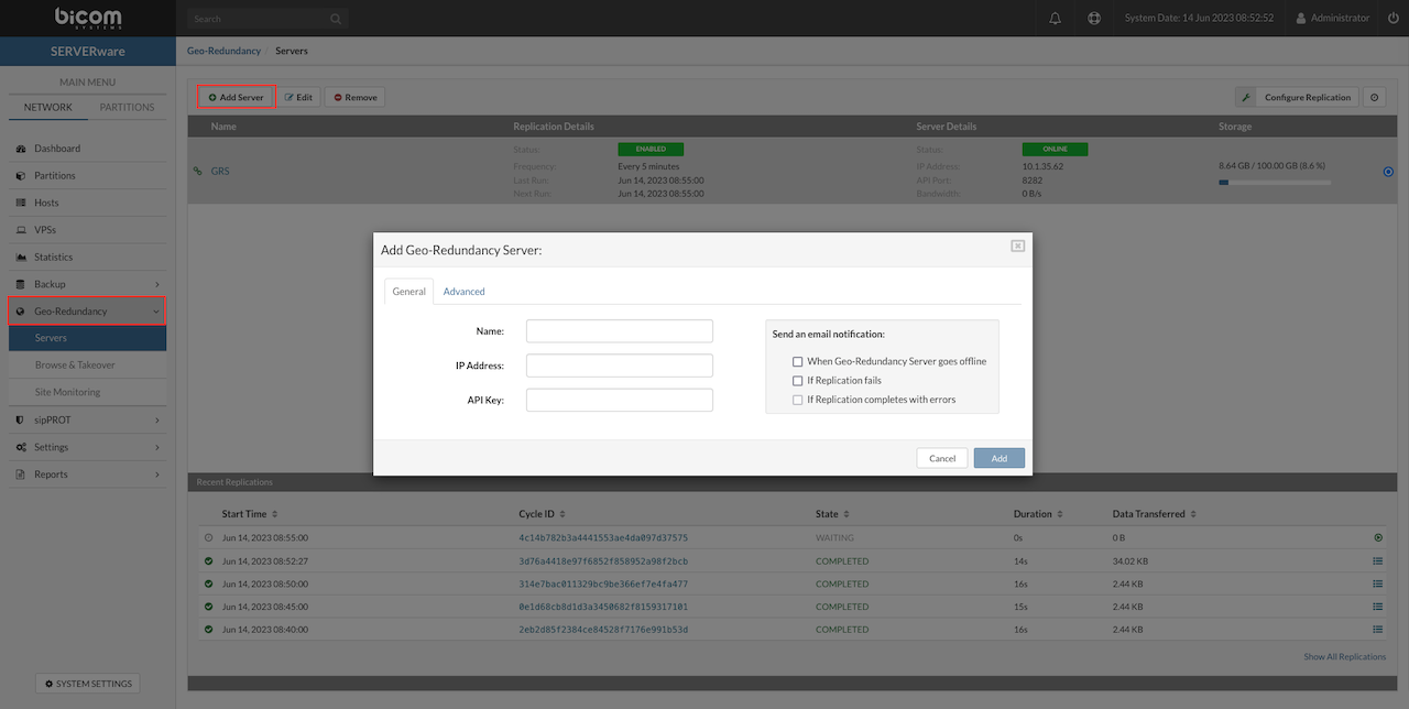
¶ Adding a Geo-Redundancy (GR) Server
To add a new Geo-Redundancy server in SERVERware, follow these steps:
-
Open the Geo-Redundancy Server Menu
From the left navigation menu, go to Geo-Redundancy, then select Servers from the dropdown. This opens the Geo-Redundancy Overview window. -
Start the Add Server Process
Click the Add Server button in the upper-left corner. A popup window will appear for entering server details.
¶ General Settings
Enter the following information:
-
Name – A custom name for the Geo-Redundancy server.
-
IP Address – IP address of the remote GR server. If the server is hosted on NETSTOR in a mirror or cluster edition, a floating IP should be used.
-
API Key – The API key used to authenticate communication with the remote site.
-
Email Notifications – Choose to receive email alerts for the following events: when the Geo-Redundancy server goes offline (due to network or hardware issues), when replication fails, or when replication completes with errors (for example, due to quota limits or missing IP addresses).
¶ Advanced Settings
Use these settings if the defaults need to be changed:
-
API Port – Port used for API communication (default is 8282).
-
Data Port – Port used for data replication (default is 7788).
-
Max Bandwidth – Set a bandwidth limit for data replication. Available options include: 1MB/s, 5MB/s, 10MB/s, 20MB/s, 30MB/s, 40MB/s, 50MB/s, 75MB/s, or Unlimited.
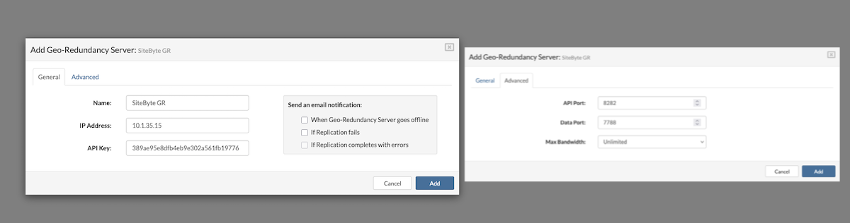
After completing all required fields, click Add to register the Geo-Redundancy server. The server will now appear in the list and will be available for replication setup and monitoring.
Please be advised that if a Geo-Redundancy (GR) server is outdated or its version is incompatible with the origin site, a notification stating "GR site is outdated!" will be displayed.
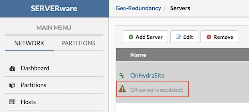
This indicates that performing a takeover on a site running an older version than the origin site may result in metadata corruption or data loss. Such replication scenarios are not recommended.
After successfully adding a new replication site, replication details can now be managed. To begin, select the desired site from the list and click Configure Replication in the upper right corner.
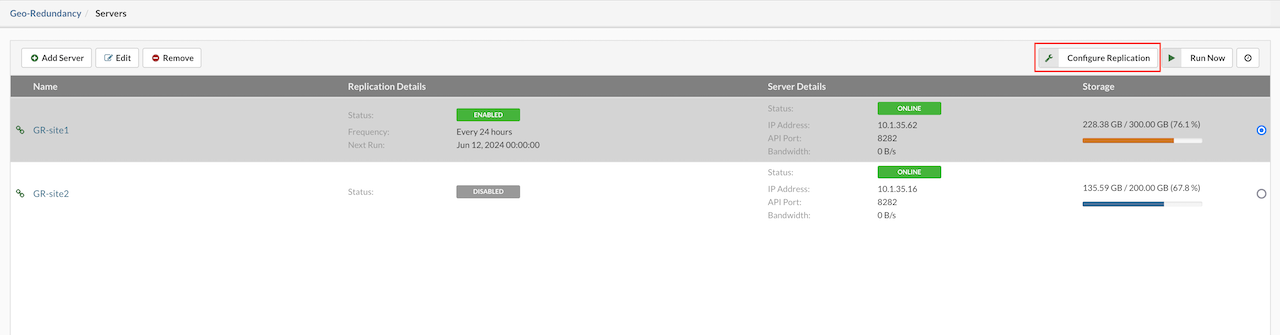
The newly opened replication configuration window is divided into two sections: General and Replicated Partitions.
¶ General Section
-
Replication – Enable or disable the replication process.
-
Replication Cycle – Choose the interval between replications in minutes from the dropdown menu. Set the desired start time using the time picker; this start time is used only for the initial replication. Based on the selected cycle, SERVERware will automatically calculate and display the scheduled time for the next replication.
-
Recovery Points to Keep – Define how many recovery points should be retained. A higher number of recovery points will require more storage space on the Geo-Redundancy Server.
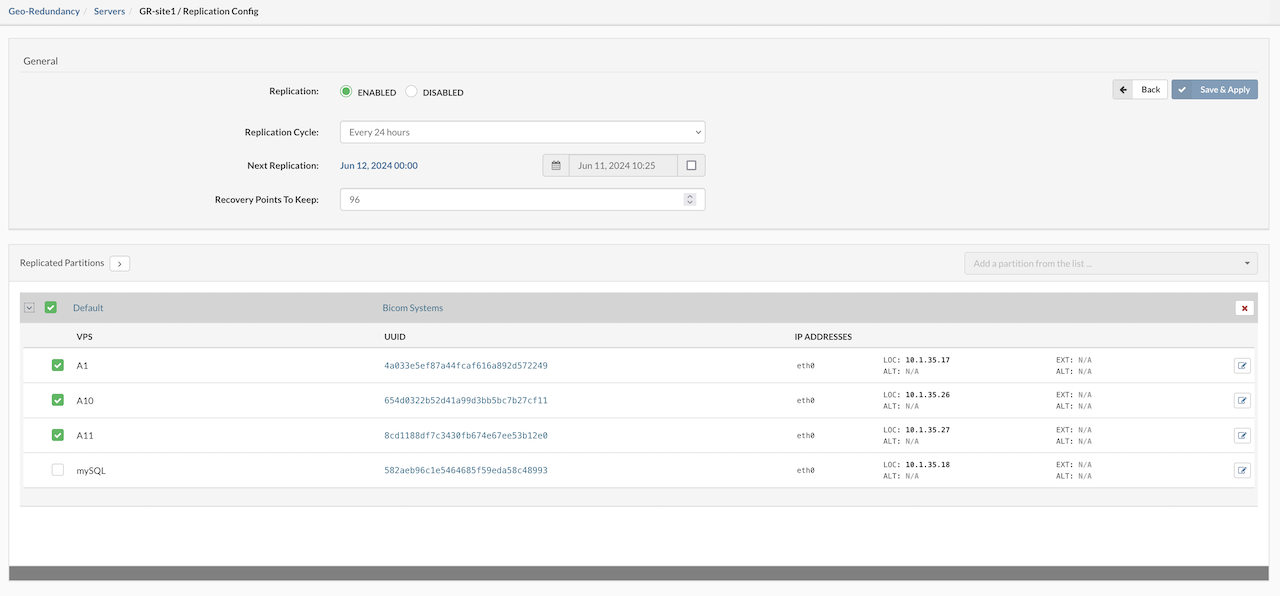
Geo-Redundancy Server will keep replications until next full circle.
¶ Replicated Partitions
In the Replicated Partitions section, use the dropdown menu on the right to select the partition that will be replicated to the remote location. Once a partition is selected, a list of VPSs from that partition will be displayed. Users can check the boxes next to individual VPSs to select them for replication, or use the checkbox next to the partition name to select or deselect all VPSs at once. To configure replication details for each VPS, locate the Edit button on the right side of the list.
Clicking the Edit button on the right opens a popup window for configuring additional settings of the selected VPS.
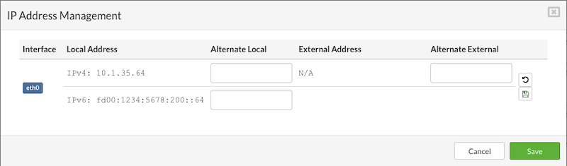
In the replication settings popup, users can configure the following network parameters for each VPS:
-
Alternate Local IP Address – Specify an alternative local IP address that the VPS will use after a takeover. This IP address must exist in the IP pool of the remote SERVERware site. If the VPS runs PBXware services, a secondary IP address must also be defined for proper functionality.
-
External IP Address – Assign an external IP address to the VPS. This should already be configured in the VPS edit menu. External IPs allow the VPS to be accessible from a public network, typically through NAT forwarding from a private IP.
-
Alternate External IP Address – Set an alternative external IP address to be used by the VPS after a takeover. The address must be part of the remote SERVERware site's IP pool. Like the primary external IP, it enables public network access via NAT.
-
Alternate Local IPv6 Address – Define an alternative IPv6 address for use after takeover. This address must also be available within the remote SERVERware site's IP pool.
Once all required fields are completed, click Save and Apply to finalize the replication settings.
The first replication will start depending on the time frame defined in configuration and it will be the "Full Replication Cycle" for every VPS selected.
Full replication is performed only during the initial replication cycle and may generate significant network traffic, potentially leading to slower system response. For this reason, it is recommended to schedule the first full replication during periods of low activity, ideally when most VPSs are idle or stopped. For Geo-Redundancy sites with complex networking configurations—such as multiple network cards and interfaces assigned to hosts and VPSs—SERVERware now supports assigning multiple alternate IP addresses for each network interface added to a VPS. This provides greater flexibility and control during replication and takeover scenarios.
¶ Recent Replications
The Recent Replications window provides an overview of the progress and status of replication cycles. It includes key replication details such as the Start Time (indicating when the cycle began), Duration of the cycle, the Amount of Data Transferred, the Maximum Transfer Rate recorded during the cycle, and the unique Cycle ID used to identify each replication instance. This information helps users monitor and evaluate the efficiency and performance of ongoing and past replication processes.
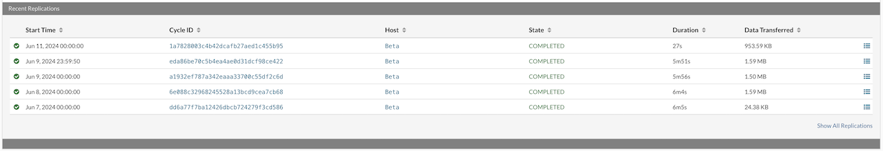
On the right side of every cycle, there is a detail view button, marked with the red square on the screenshot, when opened replication details will be displayed.
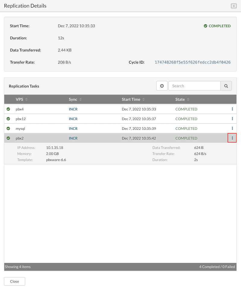
¶ Remove Geo-Redundancy Server
Before removing a Geo-Redundancy (GR) server, it is highly recommended to verify whether any active templates are running on the server. If active templates exist, they must be deleted prior to removing the GR server.
Alternatively, the server status can be set to Disabled within the Configure Replication section. Once the GR server status is disabled, users can select the server from the list and click the Remove button, located alongside the options for adding and editing servers.
NOTE: A GR server cannot be removed while active templates are still running.
¶ Browse & Takeover
The Browse & Takeover feature in SERVERware Geo-Redundancy enables administrators to monitor and assume control of Virtual Private Servers (VPS) hosted on a secondary (standby) site in the event of a failure or planned switchover from the primary site.
Through the Browse interface, all replicated VPS instances from the primary site can be listed and reviewed. When necessary, the Takeover function initiates the failover process, allowing the selected VPS to be started and managed on the secondary site, ensuring service continuity and minimal downtime.
This mechanism is critical in disaster recovery scenarios, maintenance operations, or any situation requiring manual control over high availability resources in a distributed SERVERware deployment.
Adding a replication Geo-Redundancy (GR) site is a key step for effectively using the Browse & Takeover feature. Without a properly configured replication site, VPS recovery and takeover from remote locations cannot be performed.
¶ Browse & Takeover
After successfully adding a replication site, the replicated data becomes accessible via the Browse & Takeover section.
To access this feature, navigate to Browse & Takeover within the Geo-Redundancy menu. In the upper-left corner of the interface, select the desired Geo-Redundancy Server and corresponding Origin Site. Upon selection, a comprehensive list of available replications from the specified site will be displayed for review and management.
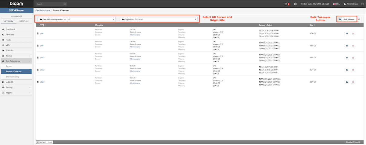
From the displayed list, select the VPS to be taken over and click the Takeover button to initiate individual restoration. To restore multiple VPS instances simultaneously, utilize the Bulk Takeover option.
¶ Takeover a Single VPS
To initiate the takeover of a single VPS:
-
Recovery Point – Choose the desired restore point from the dropdown menu.
-
Partition – Select the destination partition where the VPS will be restored.
-
Host – Choose the host that will run the restored VPS.
-
Name – Enter a name for the new VPS instance.
NOTE The right side of the window displays the original VPS metadata for reference.
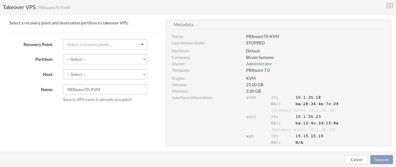
After all fields are completed, click the Takeover button in the bottom-right corner to start the process. The time required for the takeover depends on the size of the selected VPS and the storage being restored.
For virtual interfaces, IP addresses must be manually configured after the takeover. However, once the VPS is successfully taken over to the Geo-Redundancy site, any configured alternate IPs will be automatically assigned. For systems operating behind NAT, both the local and external alternate IP addresses will be automatically applied to the VPS after the takeover process is complete.
¶ Bulk Takeover
To begin a Bulk takeover, first create a list of VPSs to be taken over. Start by selecting the Geo-Redundancy Server and replication site in the upper left corner. Then, in the upper right corner, open the dropdown menu and choose Bulk Takeover. This will open a new window where it's possible to build the bulk takeover list, start the bulk operation, and save the process as a template for future use.
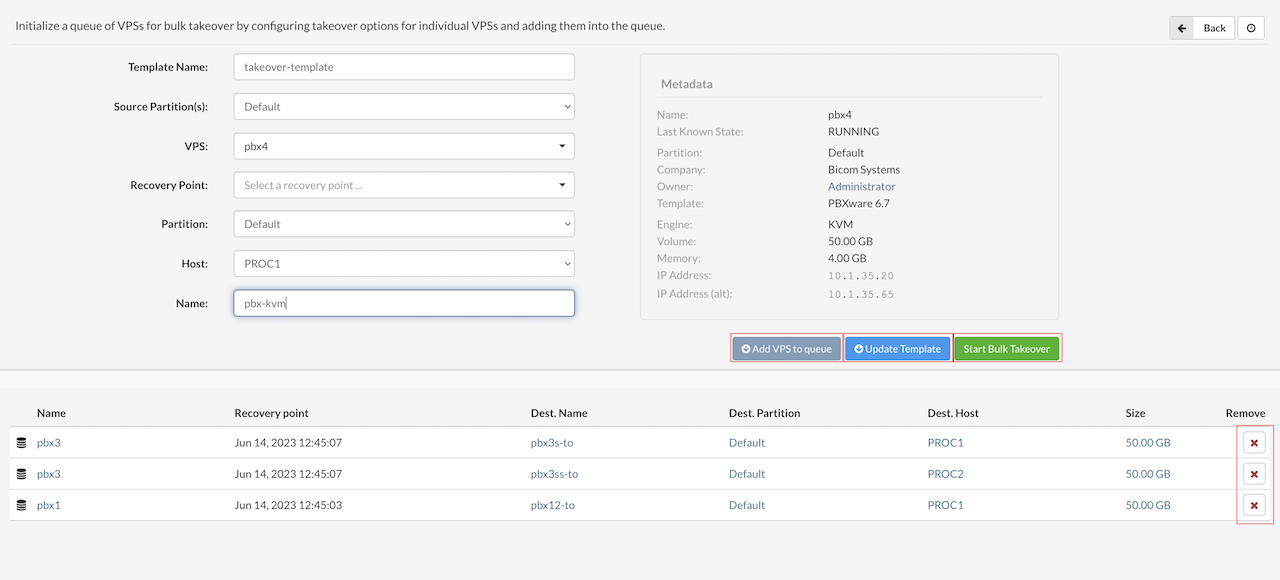
In the Bulk Takeover window, users can add VPSs to the takeover action by following these steps:
-
Template Name: Enter a name for the takeover template.
-
Source Partition(s): Select the source partition of the VPS to recover.
-
VPS: Choose the VPS from the drop-down list.
-
Recovery Point: Select the recovery point for the VPS. (Note: If the operation is saved as a template, this will automatically populate with the latest available point.)
-
Partition: Select the destination partition for the VPS.
-
Host: Choose the destination host for the VPS.
-
Name: Specify a name for the VPS. (This is automatically populated from metadata but can be edited. Duplicate names are not allowed.)
Once all fields are filled, users can press Add VPS to queue to add the VPS to the list below. This process can be repeated for all VPSs in the replication database.
During the takeover process, users can cancel the takeover of a single VPS, several VPSs, or all ongoing takeovers at once with just one click. This makes it easy to manage and adjust the process whenever needed.
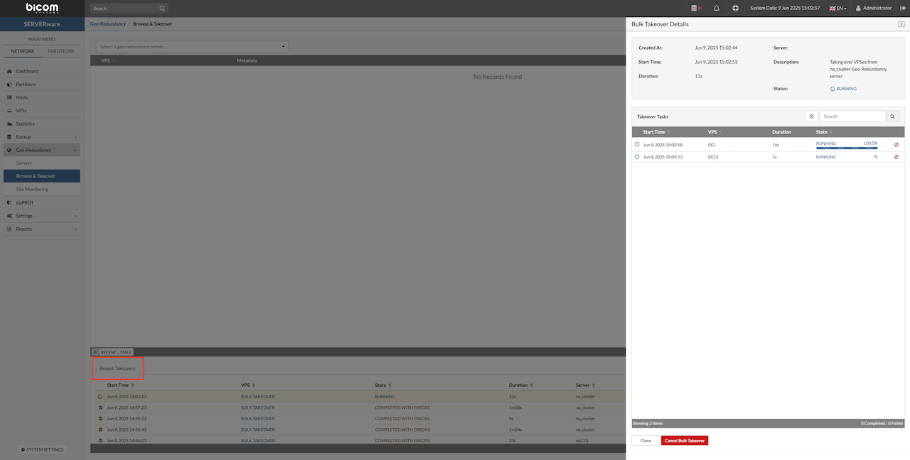
Recent Takeover Window
Once the takeover process has started, its progress and details can be tracked in the Recent Takeovers window. This view provides real-time updates on the status of each takeover task, allowing users to monitor ongoing operations and ensure everything is proceeding smoothly.
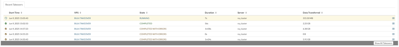
Bulk Templates
Once the VPS list is complete, users have two options: either save the list as a template to run later by clicking Save Template (templates can be modified later in the saved templates window), or start the bulk takeover immediately by clicking Start.
The Saved Templates window displays a list of all bulk takeover templates stored on the server. From this window, users can easily manage templates by editing their details or deleting those that are no longer needed.
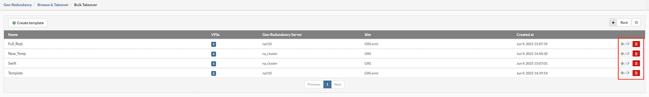
Once the takeover process is complete, the restored VPS is ready to use and can be managed from the VPSs section in the main menu. The VPS is now running on the takeover site with all data and settings restored from the selected recovery point. This finishes the takeover process and the VPS is available for normal operation.
¶ Remove Replicated VPSs
SERVERware administrators can easily remove outdated or unnecessary VPS replications from the Geo-Redundancy (GR) pool by selecting the desired replication and clicking the Remove button. This action does not affect the VPS on the production site, nor does it impact any VPSs currently running on the GR site. After removal, the VPS will be fully replicated again during the next replication cycle.
To remove a VPS replication, select the VPS and click the Remove button. A confirmation dialog will appear to verify the removal.
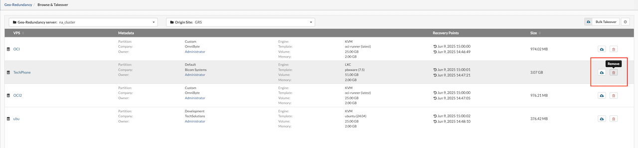
For replications older than two weeks, the administrator will see a warning icon indicating that the snapshot in question has data that hasn't been resynced for the above mentioned time frame.
¶ Site Monitoring
Site monitoring in SERVERware lets administrators keep an eye on remote replication sites by running tests that check if the site is up and running. If any problems are detected, the system can automatically trigger actions based on the test results.
Actions can be set to run either when all tests fail (ALL action type) or when just one test fails (ANY action type), giving flexibility in how issues are handled. This feature helps ensure that replication sites stay reliable by catching problems early and responding quickly, which reduces downtime and keeps data safe.
To create and manage site monitoring, select Site Monitoring from the Replication menu. Also other options are available:
-
Create Site Monitor — Opens a new window to set up a site monitor by defining tests to run and actions to trigger.
-
Edit — Modify an existing site monitor (note: the monitor must be stopped before editing).
-
Remove — Delete an existing site monitor (the monitor must be stopped before removal).
-
Start — Activate the site monitor to begin running tests and triggering actions.
-
Stop — Pause the site monitor and its actions.
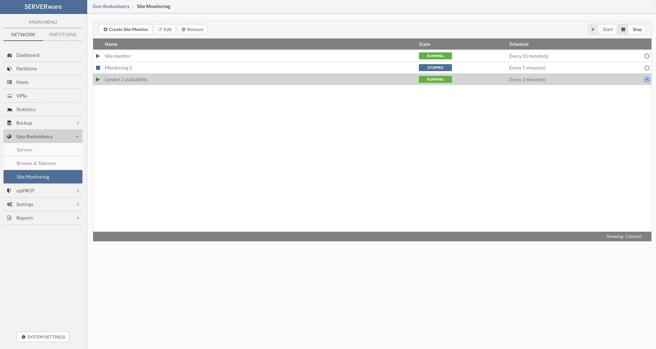
¶ Create Site Monitoring
Pressing the Create Site Monitor button opens the site monitor setup window. Here, users can add tests to check if the remote site is available and set actions that will run if those tests fail. This lets users customize what to monitor and how to respond if there's a problem.
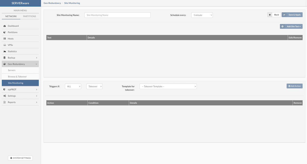
Here is how to set up a new site monitor:
-
Site Monitoring Name: Enter a clear, short name that describes the site being monitored for easy identification.
-
Schedule every: Choose how often the tests will run from the dropdown menu. For example, if set to 1 minute, all tests will run every minute. If a test takes longer than the set time, the next cycle will wait until the current tests finish.
-
Save & apply: After naming the monitor and setting the schedule, save it to be able to add tests and triggers.
¶ Add Site Test
To add a new test to the monitor, click Add Site Test. This opens a popup where test details can be configured. The following options are available for configuration:
¶ ICMP Test Parameters
The ICMP test checks if a remote system is reachable by sending basic ping requests and waiting for replies. It helps confirm that the target site is up and responding.
In SERVERware, this test can be adjusted with extra settings. Users can set how many ping packets to send, how long to wait for a reply, how much packet loss is acceptable, and what the maximum average delay (latency) should be. Users can also define how many network hops the ping is allowed to make.
These settings let admins keep an eye on basic network health. If something starts to go wrong—like high latency or lost packets—the test can fail and trigger an action. It's a simple way to watch over remote sites and get alerts when there's trouble.
Possible command options and success conditions include:
-
Destination: Set the target for the ICMP test. This can be an IP address or a partition name.
-
Packet Count: Number of echo requests (pings) to send.
-
Test Timeout (seconds): Maximum time allowed for the test to run before it stops.
-
Packet Delay (ms): Time in milliseconds between each ping. Setting this very low sends pings continuously.
-
TL (Time to Live): Number of hops allowed before the ping is discarded. For example, setting it to 10 lets the ping pass through up to 10 routers.
-
Packet Size (bytes): Number of data bytes sent in each ping. Default is 64 bytes (56 bytes data + 8 bytes ICMP header).
-
Maximum Loss (%): Maximum allowed packet loss percentage before the test fails.
-
Max Average Latency (ms): Maximum allowed average latency in milliseconds. If latency exceeds this value, the test fails.
-
Timed Out: If enabled, the test will ignore the Test Timeout value.
-
Invert Result: When enabled, a failed test will be marked as successful, and vice versa.
-
Dry Run Button: Runs a trial test and shows results — green bar for success, red bar for failure.
-
Cancel Button: Discards changes and closes the window.
-
Update Button: Saves changes and closes the window.
The image below shows examples of test results, including both successful and failed outcomes.
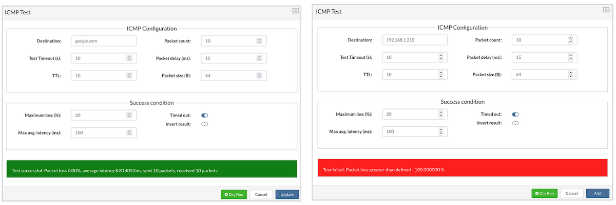
¶ HTTP Test Parameters
The HTTP test uses standard request types such as GET, HEAD, POST, PUT, and DELETE to verify whether a remote service is available and functioning properly. Users can define specific success conditions to evaluate the server's response.
This test is commonly used to confirm that a service on the remote site is reachable and responding as expected. For example, a GET request can check if the service returns the correct status code or expected content, while a POST request can confirm the server accepts and processes data correctly.
Users may configure the test to evaluate success based on response code, response content, or the time it takes to get a reply. This flexibility allows reliable monitoring of web-based services at the replication site.
Available request types and additional conditions include:
-
URL - Enter the full destination URL. It's important to include either http:// or https:// at the beginning of the address.
-
Request Type:
-
GET – Requests data from the specified resource. No data is sent with the request.
-
HEAD – Only retrieves headers from the specified URL, not the content.
-
POST – Sends data to the server. Commonly used to submit forms or API data.
-
PUT – Creates or updates a resource with the provided data.
-
DELETE – Removes the specified resource.
-
-
Test Timeout (s): This sets how long the test will wait for a response before failing. If the time runs out, the test is marked as failed.
-
Verify SSL: Enabling this checks if the destination URL has a valid and trusted SSL certificate.
-
Headers: Custom headers can be added to the request. Each header has a name and a value.
Example:
Name: Authorization
Value: Basic U0VSVkVSd2FyZTpleGFtcGxl
- Arguments: These are added as query parameters to the URL. Each argument includes a name and a value.
Example:
Name: query
V_alue: SERVERware
- Body: This section is for entering raw request content, like JSON data.
Example:
{
"name": "SERVERware",
"version": 4
}
-
Response Code: Specify which HTTP response code(s) are expected. If the actual response doesn't match, the test will fail.
Codes are grouped as:-
100–199: Informational
-
200–299: Success
-
300–399: Redirect
-
400–499: Client errors
-
500–599: Server errors
-
-
Response RegExp: Add a regular expression to check the response content.
Example: A test passes if the response contains the word SERVERware.
-
Invert Result: Enable this to reverse the test result. A failed test will be marked as passed and vice versa.
-
Dry Run: Runs the test once to check if it behaves as expected. A green bar means success, red means failure.
-
Cancel: Discards any changes and closes the window.
-
Update: Saves and applies the test configuration.
This setup allows for precise and flexible monitoring of HTTP services, ensuring accurate tracking of remote site health and behavior.
¶ TCP Test Parameters
TCP (Transmission Control Protocol) is a core transport protocol used alongside IP (Internet Protocol), commonly referred to together as the TCP/IP stack. While IP is responsible for delivering packets across networks, it does not guarantee order or delivery. TCP fills this gap by ensuring reliable communication between two systems. It handles tasks like detecting lost packets, re-sending them if needed, removing duplicates, and making sure data arrives in the correct order. This makes TCP ideal for applications that need dependable, consistent data delivery across networks.
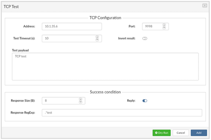
To configure a TCP test, the following settings are available:
-
Address: Enter the destination IP address where the TCP test will be sent.
-
Port: Specify the target port number for the connection.
-
Test Timeout (s): Set the maximum time in seconds the test is allowed to run before stopping automatically.
-
Invert Result: When enabled, it flips the outcome of the test — a failed test will be treated as successful, and vice versa.
-
Test Payload: This is the actual data that will be sent in the TCP packet.
-
Response Size (B): Define the expected size (in bytes) of the reply payload. The test will pass only if this size matches the response received.
-
Response RegExp: Use a regular expression to evaluate whether the response content meets a specific pattern or condition.
-
Reply: When this is turned on, the test will check the response payload using the size and regular expression settings.
-
Dry Run: Runs a test instantly and displays the result. If successful, the result will show in green; if it fails, it will be shown in red.
-
Cancel: Closes the configuration window without saving any changes.
-
Add / Update: Saves the current test configuration and closes the popup.
¶ UDP Test Parameters
The User Datagram Protocol (UDP) is a lightweight transport-layer protocol that works without creating a connection between devices. It acts as a direct interface between the IP layer and applications, using ports to differentiate multiple services running on the same device.
Unlike TCP, UDP doesn't provide reliability, flow control, or error correction. It sends data without checking if it arrives or in what order. This simplicity means UDP packets are smaller and require less overhead, making it faster and more efficient in situations where speed matters more than reliability.
UDP is commonly used by applications where some data loss is acceptable or handled by the application itself. It's the transport layer for protocols like DNS, SNMP, NFS, and TFTP.
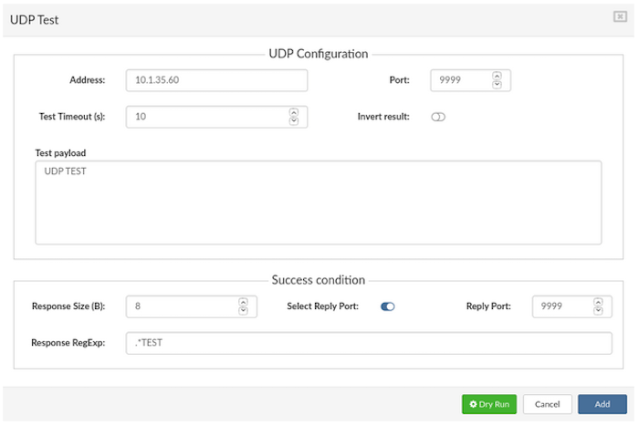
To configure a UDP test, fill in the following parameters:
-
Address: Enter the destination IP address where the test will be sent.
-
Port: Set the target port number.
-
Test Timeout (s): Defines the maximum time the test will run. If this time is exceeded, the test is stopped.
-
Invert result: When enabled, test results are flipped — a failed test will be marked as passed, and vice versa.
-
Test payload: Input the data that will be sent as the payload in the UDP packet.
-
Response Size (B): Expected size of the response payload in bytes. If the actual response matches this size, the test is considered successful.
-
Response RegExp: A regular expression that will be used to check the response content. Useful for advanced validation of response data. (More on regex: https://en.wikipedia.org/wiki/Regular_expression)
-
Select Reply Port: When enabled, a specific reply port will be used as part of the test success condition.
-
Dry Run Runs the test immediately to preview results. A green bar means success, red means failure.
-
Cancel: Discards changes and closes the test configuration window.
-
Add / Update: Saves the current configuration and closes the window. Use Add for new tests or Update to modify existing ones.
¶ MMonit Integration
Starting from SERVERware version 4.3, M/Monit is integrated into the platform. It works alongside Monit, which acts as the agent on each system. This setup allows centralized monitoring and management of all SERVERware hosts and services using M/Monit directly from within SERVERware.
A new option — MMonit — is available in the Add Site Test dropdown menu, making it easy to include M/Monit checks as part of Site Monitoring.
To set up monitoring with M/Monit:
-
In the Site Monitoring Name field, enter a clear name for the monitor (for example, “MMONIT”).
-
Set the Schedule time — this defines how often the test will run.
-
Click Save and Apply to confirm. A popup window will open.
Next, to create the test:
-
Click Add Site Test.
-
From the dropdown menu, select MMonit as the test type, and a popup window will apear.
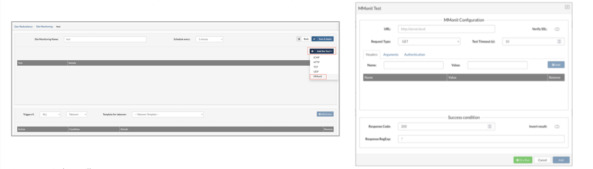
To configure the MMonit test in SERVERware Site Monitoring, fill in the fields as follows:
Request/Headers Setup
-
URL:
http://:8080/api/1/reports/events/list
(Replace with the actual IP address of MMonit server) -
Request Type:
GET
(As required by the MMonit API documentation) -
Test Timeout:
10 seconds
(If no response is received within this time, the test will fail)
Arguments
Under the Arguments tab, add the following:
Name: z_csrf_protection
Value: off
Name: state
Value: 1
(This filters the API response to include only failed events)
Authentication
In the Authentication tab, provide:
Username and Password for the MMonit user
(Use the same credentials used to log into the MMonit web interface)
Success Conditions
Under Success Conditions, set:
Response Code: 200
(This is the expected response for a successful API call)
Response RegExp:
Enter a regular expression to search for the hostname that was previously configured in MMonit.
(This confirms the test is reaching the correct data in the response)
This setup allows SERVERware to query MMonit for failed events and trigger alerts or actions if failures are detected.
To verify the setup, click the Dry Run button. If everything is configured correctly and there are no current failures in MMonit, the result should display Test successful.
Once the test passes, click Update to save it to the list of configured tests.
¶ Create Actions
-
Add Action: Click this to add a new action to the action list with preselected options.
-
Triggers if: Choose when the action should be triggered. Two conditions are available:
-
ALL– The action is triggered only if all configured tests for the site fail.
-
ANY – The action is triggered if any one of the tests fails.
-
Alarm: Select the Alarm action to be triggered when the selected condition is met.
Once triggered, the alarm will appear on the SERVERware dashboard and an email notification will be sent to the administrator.
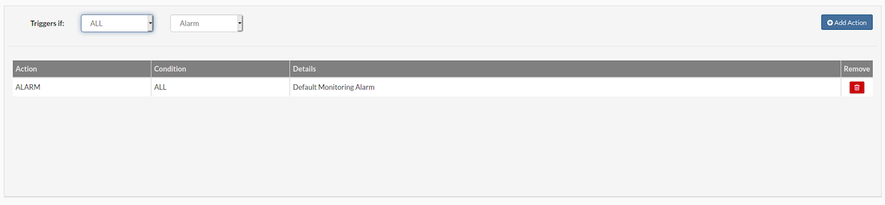
¶ Control Geo-Redundancy Server Resources (GR Site B)
Please be advised that if a Geo-Redundancy (GR site B) server is outdated or its version is incompatible with the origin site, it is strongly recommended to update it to the latest version. Performing a takeover on a site running an older version than the origin site may lead to metadata corruption or data loss.
¶ Managing Geo-Redundancy Server Resources
The Geo-Redundancy Server (GRS) has its own dedicated setup and configuration for managing services. Access to these services is controlled through API keys and Access Control Lists (ACL), which define authentication and authorization rules.
There are two main scenarios for how the GRS is used:
Basic Data Redundancy Between Sites
In this scenario, SERVERware installations on both the primary site and the failover (takeover) site connect to the GRS using an administrator API key. This setup gives the administrator full control, allowing them to browse all replicated data on the GRS and perform VPS takeovers from any connected site. The administrator can choose to restore a VPS to its default location or to a specific partition based on need. This approach is ideal for environments where the same organization manages both primary and backup sites and needs full control over replication and failover operations.
Hosting Data Redundancy Managed by a Provider
Here, the SERVERware installation on the primary site connects to the GRS using a user-level API key. The hosting provider controls the GRS and manages takeover operations. The provider supplies the necessary credentials and IP address to connect to the Geo-Redundancy Server. This model is common for service providers offering disaster recovery or hosting services to multiple clients, where the provider controls failover and resource management, while clients have limited direct access.
Additional Notes:
-
API Keys: These keys are essential for securely authenticating requests to the Geo-Redundancy Server. Administrator keys have broad permissions, while user keys have limited rights based on assigned ACLs.
-
Access Control Lists (ACL): These lists define what actions each API key can perform, such as browsing data, initiating takeovers, or modifying replication settings.
-
Resource Management: The GRS handles replication storage and VPS images, ensuring data consistency and availability between sites. Administrators or providers can configure how replication data is stored, managed, and recovered during failover.
-
Security Considerations: Limiting access through ACLs and API keys helps maintain a secure environment, especially when multiple sites or providers are involved. Proper management of keys and permissions is critical.
In summary, the Geo-Redundancy Server acts as a centralized hub for data replication and failover control, with flexible access models to support both internal and hosted disaster recovery setups.
¶ Manage Replication Service
To manage the replication service, the command-line tool swrepl-adm is used via SSH.
Connect to the server using an SSH client (such as Putty) with these settings:
-
Host IP address (e.g., 232.123.44.108)
-
Port: 2222
-
Login as root
-
Password: serverware
NOTE In mirror or cluster storage server setups, connect using the floating IP to reach the active primary server automatically.
Replication storage must reside on the storage host within the NETSTOR pool. For the Geo-Redundancy Server, storage is considered an SSD-based pool.
After logging in, basic server information will appear. From there, swrepl-adm commands allow configuration and control of the replication service.
Example :
  ███████╗██╗    ██╗      ██╗  ██╗
 ██╔════╝██║    ██║      ██║  ██║
 ███████╗██║ █╗ ██║█████╗███████║
 ╚════██║██║███╗██║╚════╝╚════██║
 ███████║╚███╔███╔╝           ██║
 ╚══════╝ ╚══╝╚══╝            ╚═╝

 * SERVERware system IP Address/es:
 * 127.0.0.1/x 192.168.x.x/x 10.1.x.x/x 192.168.x.x/x


 * Login into the setup by visiting:
 * https://127.0.0.1:81/
 * https://192.168.x.x:81/
 * https://10.1.x.x:81/
 * https://192.168.x.x:81/

 ~ #
Start using the SWREPL application by running the command :
~ # swrepl-adm
The swrepl-adm console will be opened in the terminal and we can start creating a site for replication.
¶ The list of commands supported
site { COMMAND | help}
COMMAND :#
- - add -storage -quota [KMGT] -throttle [KMGT] -admin=true/false -allowedips ... "quoted description text"
Add replication site with description, optional set storage quota, throttling in bytes per second,
and allowed IPs (default allows all).
- -allowed IPs specify quoted the comma ',' separated list of IPs or subnets in CIDR format
e.g. "192.168.1.10, 10.1.0.0/16, 2001:db8:a0b:12f0::1/32"
default value 0.0.0.0/0 in the list means allow all
- - update -storage -quota [KMGT] -throttle [KMGT] -admin=true/false -allowedips ... "quoted description text"
Update replication site with description, optional set storage quota, throttling in bytes per second,
and allowed ips (default allows all).
- - list [id] List sites, showing unique id and other settings.
- - remove [-force] id Remove site by its unique id
replication { COMMAND | help}
COMMAND :#
-
- list [id] Show the list of all defined replications for this daemon.
-
- help Show help.
-
public_key { help } Output own rsa public key.
-
admin_key {set newkey} { help } Output or set current admin API key.
-
task { COMMAND | help}
COMMAND :#
-
- list [-l, -t backup] [id] List tasks, showing unique id and other settings.
-
-l - Limit list size (default is 10, 0 for unlimited)
-
-t - filter tasks of specific type backup,replication or srv_backup,srv_repl
-
id - id of task for detailed output
-
- cancel id Cancel task by its id
To set up a Geo-Redundancy Server (GRS) site, the first step is to create a dedicated ZFS dataset.
This dataset should be created on the storage host, specifically within the NETSTOR ZFS pool. When allocating space, ensure the available capacity is at least double the total size currently used by all VPSs included in the replication group. Only SSD-backed storage pools should be used for the Geo-Redundancy dataset to ensure performance and reliability.
ZFS file systems are created using the zfs create command. The syntax for creating a dataset follows this structure:
pool-name/[filesystem-name/]new-filesystem-name
The pool-name (e.g., NETSTOR) defines the root, and any optional intermediate names help organize the dataset hierarchy. The final segment is the name of the new dataset.
For example, to create a dataset named GRS in the NETSTOR pool:
This command creates a new dataset named GRS under the NETSTOR pool, which will be used to store replicated VPS data for the Geo-Redundancy Server.
~ # zfs create NETSTOR/GRS
ZFS automatically mounts the newly created file system if it is created successfully. By default, file systems are mounted as /dataset, using the path provided for the file system name in the create subcommand. In this example, the newly created Geo-Redundancy Server file system is mounted at /NETSTOR/GRS.
Execute zfs list command to ensure dataset is created:
~ # zfs list
NAME                                                                                     USED  AVAIL  REFER  MOUNTPOINT
NETSTOR                                                                                  489G   156G   142M  /NETSTOR
NETSTOR/CONTROLLER                                                                      1.38G   156G  1.38G  /NETSTOR/CONTROLLER
NETSTOR/GRS                                                                              483G   156G   112K  /NETSTOR/GRS
NETSTOR/logs                                                                             476K  8.00G   476K  /NETSTOR/logs
NETSTOR/templates                                                                       3.60G   156G    96K  none
SYSTEM-e274                                                                             10.1G   205G    96K  none
SYSTEM-e274/BACKUP                                                                        96K   205G    96K  legacy
SYSTEM-e274/rootfs                                                                      6.63G  8.37G  4.63G  /
SYSTEM-e274/rootfs/log                                                                   118M  1.89G   118M  legacy
SYSTEM-e274/swap                                                                        2.13G   207G    60K  -
After this continue with creating the 8145EEE4 site. On the selected host run swrepl-adm CLI tool.
~ # swrepl-adm
»
Space used for the Geo-Redundancy dataset should be 60% of the storage space available, this way we will secure there is enough space left for replications.
When in the "swrepl-adm" console we can use CLI commands to create a new site to do this we will type :
» site add -storage NETSTOR/GRS -quota 450G -throttle 70M  -admin=true  -allowedips "192.168.1.10,10.1.0.0/16"  "this is my site"
OK 93010f9f4003723d2eec317bf7160e0d
In the list of allowed IPs the remote Controller IP, and the Storage Host IP addresses must be allowed. The best practice is to add the whole subnet of the cluster.
The site with ID: 93010f9f4003723d2eec317bf7160e0d is created, to confirm the site parameters type:
» site list
      ID     |      INFO       | ADMIN |   STORAGE   |   QUOTA   | THROTTLING
+------------+-----------------+-------+-------------+-----------+------------+
  93010f9... | this is my site | false | NETSTOR/GRS | 450.0 GiB   | 70.0 MiB/s
+------------+-----------------+-------+-------------+-----------+------------+
All available sites will be displayed, for a more detailed view add site ID after the command:
» site list 93010f9f4003723d2eec317bf7160e0d
    ID:          93010f9f4003723d2eec317bf7160e0d
    Description: this is my site
    Admin:       true
    API Key:     7e0f6463412acc17d3ff163065c1d897
    Storage:     NETSTOR/GRS
    Quota:       450.0 GiB
    Throttling:  70.0 MiB/s
    Allowed IPs: 192.168.1.10,10.1.0.0/16
To edit the site parameters after the creation site update command can be used:
For example change allowed IPs:
» site update 93010f9f4003723d2eec317bf7160e0d -allowedips 0.0.0.0
OK
» site list 93010f9f4003723d2eec317bf7160e0d
    ID:          93010f9f4003723d2eec317bf7160e0d
    Description: this is my site
    Admin:       true
    API Key:     7e0f6463412acc17d3ff163065c1d897
    Storage:     NETSTOR/GRS
    Quota:       450.0 GiB
    Throttling:  70.0 MiB/s
    Allowed IPs: 0.0.0.0
If the details on the site are correct we can use API Key: 7e0f6463412acc17d3ff163065c1d897 to connect the SERVERware to our newly created site and start the replication process.
If there is failure on primary site after failover and restore to remote location, to return data to primary site, using the same procedure we will create Geo-Redundancy dataset on storage host (Site - A) and return data to primary location.
¶ Geo-Redundancy Dataset on the Backup host
To create a new dataset log-on the Backup Host
- Find out the name of the pool by typing:
~ # zpool status | grep pool
pool: SYSTEM-e694
- When we know the name of the zfs pool we can create a dataset for Replication storage we will use the name of the pool from the previous command "SYSTEM-e694" add trailing slash / and dataset name, in our case "GRS" so the command will look like this:
~ # zfs create SYSTEM-e694/GRS
- Next, we need to create the mount point and boot parameters for the new dataset
~ # zfs set mountpoint=legacy SYSTEM-e694/GRS
~ # zfs set overlay=on SYSTEM-e694/GRS
- Create a directory and mount our newly created ZFS dataset.
~ # mkdir /GRS
~ # mount -t zfs SYSTEM-e694/GRS  /GRS
- We should add this mount point to the "/etc/fstab" so the SERVERware mounts this dataset after reboot.
~ # cat /proc/mounts | grep GRS

SYSTEM-e694/GRS /GRS zfs rw,relatime,xattr,noacl 0 0
The output of the last command should be copied into /etc/fstab.
~# nano /etc/fstab

# /etc/fstab: static file system information.
#
# noatime turns off atimes for increased performance (atimes normally aren't
# needed); notail increases the performance of ReiserFS (at the expense of storage
# efficiency).  It's safe to drop the noatime options if you want and to
# switch between notail / tail freely.
#
# The root filesystem should have a pass number of either 0 or 1.
# All other filesystems should have a pass number of 0 or greater than 1.
#
# See the manpage fstab(5) for more information.
#

# <fs>                  <mountpoint>    <type>          <opts>          <dump/pass>

# NOTE: If your BOOT partition is ReiserFS, add the notail option to opts.
systemd                      /sys/fs/cgroup/systemd	  cgroup    rw,relatime,name#systemd  0 0

/dev/zvol/SYSTEM-e694/swap        none           swap	   defaults              0	0
SYSTEM-e694  /rootfs/log       /var/log       zfs       rw,relatime,xattr     0	   0
SYSTEM-e694/GRS /GRS zfs rw,relatime,xattr,noacl 0 0
After the editing saves the file and exit.
-
Reboot the backup host.
-
After the host, reboot log on and inspect dataset and mount point we have just created in ZFS
~ # zfs list
NAME                                                                                         USED  AVAIL  REFER  MOUNTPOINT
SYSTEM-e694                                                                                  117G   225G    19K  none
SYSTEM-e694/GRS                                                                               24K   225G    24K  legacy
SYSTEM-e694/rootfs                                                                          7.10G  7.90G  5.10G  legacy
SYSTEM-e694/rootfs-prev                                                                     4.94G  10.1G  4.94G  /
SYSTEM-e694/rootfs/log                                                                      24.9M  1.98G  24.9M  legacy
SYSTEM-e694/swap                                                                            2.13G   227G    12K  -
If we can see a new dataset as shown (SYSTEM-e694/GRS 24K 225G 24K legacy) we have successfully created a new dataset and we can continue setting up the Replication users.
¶ sipPROT
¶ Introduction to sipPROT
¶ What is sipPROT?
sipPROT is a security tool developed by Bicom Systems to protect VoIP systems from SIP-based brute-force attacks. It's designed to monitor and react to suspicious SIP activity in real time, blocking unwanted or potentially harmful traffic before it becomes a problem.
sipPROT can be installed in two environments:
-
On standalone PBXware systems, where it runs directly on the hardware.
-
On SERVERware hosts, where PBXware is deployed as a VPS—sipPROT should be installed on each host to ensure full protection.
¶ How It Works?
When sipPROT detects unusual or repeated failed SIP registration attempts, it automatically blocks the offending IP address using firewall rules. These blocks are temporary by default, but if the same IP triggers multiple alerts, it can be permanently banned.
sipPROT doesn't rely on logs—it works by analyzing live SIP traffic, which makes it more accurate and faster at detecting threats compared to other solutions. It also includes Geo-IP filtering, letting administrators block or allow traffic based on country. This can be useful for minimizing exposure to regions known for frequent attack attempts.
¶ What It Helps Prevent?
-
Repeated unauthorized SIP login attempts
-
Service downtime caused by denial-of-service-type brute-force activity
-
Possible credential theft through SIP registration abuse
¶ Key Capabilities
-
Live Traffic Analysis: Monitors SIP packets in real time to spot and stop attacks immediately.
-
Smart IP Blocking: Automatically blocks attackers with temporary or permanent bans.
-
Geo-IP Filtering: Optional location-based blocking adds another layer of protection.
-
Firewall Integration: Updates firewall rules directly without needing manual intervention.
sipPROT adds a critical line of defense to VoIP systems, helping ensure availability and reducing the risk of financial or service disruption due to SIP attacks.
When sipPROT is running, please DO NOT delete any "extension" on PBXware before registered phone on extension is "RESET" to factory settings; otherwise, sipPROT will block IP addresses along with all the phones registering from that IP. Notification about blocked IPs will be sent to the e-mail, set under the Notification Recipients tab, assuming that SMTP settings are correct.
¶ sipPROT Dashboard
The sipPROT dashboard is designed to provide critical information regarding the health and status of the protection system. Here's a brief overview of what each widget on the dashboard likely represents:
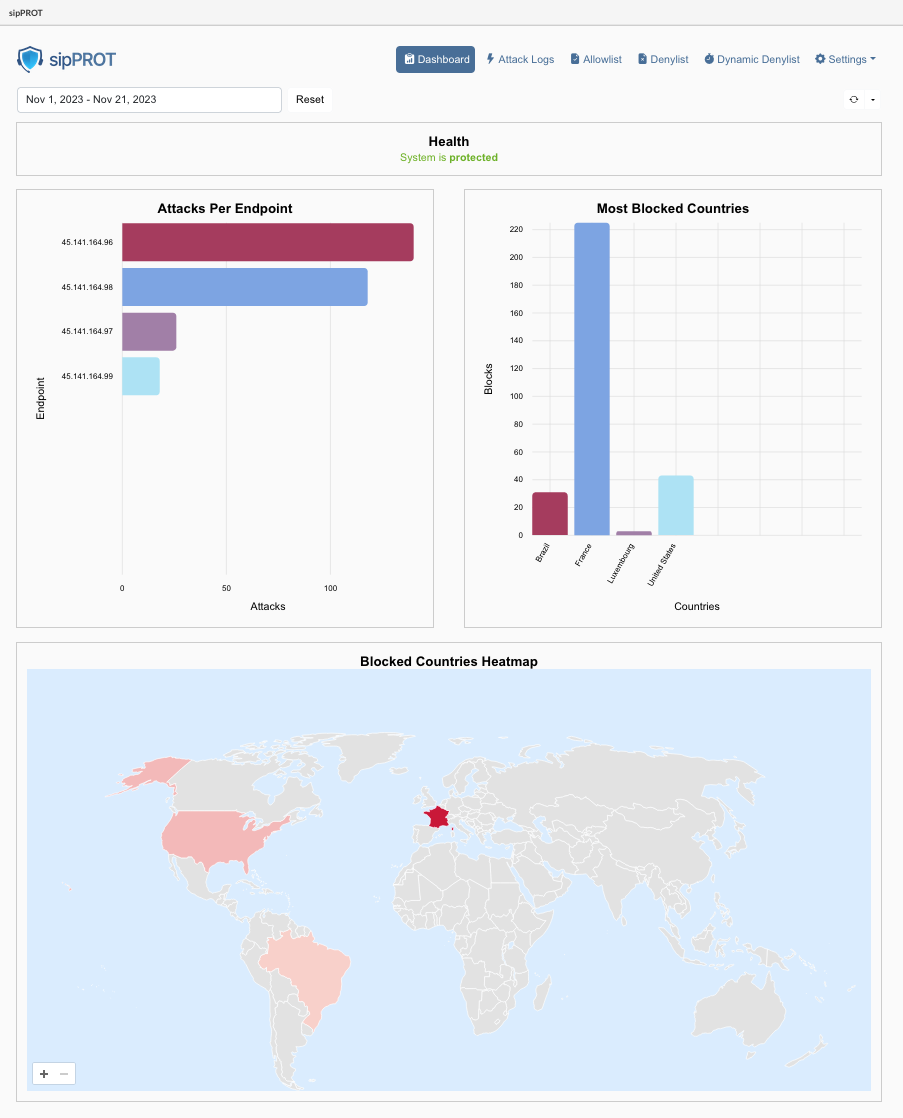
| Widget | Description |
|---|---|
| Health: | This widget displays the health status of the sipPROT service. It indicates whether the service is running smoothly or if there are any issues. If there are problems detected, users are prompted to check the hosts page for more details. A direct link to the hosts page is also provided for quick access. |
| Prompted Message: | System is protected: System did not detect any health issues. |
| Prompted Message: | Issues detected: Please check the hosts page via direct link or from the menue to see details. |
| Attacks Per Endpoint: | This widget shows a list of attacks for a specified time period, helping to identify which IP addresses or Virtual Private Servers (VPS) are most targeted on user's server. For PBXware users, this will typically show attacks on a consistent IP address. |
| Most Blocked Countries: | This widget displays information about the origin countries of blocked IP addresses. It groups blocked IPs based on their country of origin, providing insights into geographic patterns in the attack data. |
| Blocked Countries Heatmap: | A geolocation heatmap that visually represents the density or intensity of attacks based on geographic location. It uses color coding to indicate areas with higher and lower concentrations of attacks. Warmer colors indicate higher concentrations of attacks, while cooler colors indicate lower concentrations. |
| All these widgets are affected by the date picker filter and the refresh time selector on the dashboard. This means users can customize the displayed data based on specific time frames and set how frequently the information is updated. | |
| Each widget provides valuable insights into different aspects of the security and health of the system managed by sipPROT, making it easier for users to monitor and respond to potential threats or issues. |
¶ sipPROT Settings
General sipPROT configuration can be found under menu Settings > Firewall.
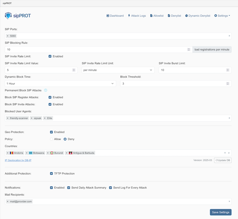
¶ The description for the options available:
| Field | Description |
|---|---|
| SIP Ports: | Specify one or more ports or ranges to monitor, such as "5060" or "5060:5062". |
| SIP Blocking Rule: | Set the maximum number of unauthorized registration attempts per minute before blocking an attacker's IP address for a specified amount of time. |
| Dynamic Block Time: | Choose how long blocked IP addresses will remain blocked after preventing an attack. |
| Block Threshold: | Define how many times an IP address will be dynamically blocked before it is permanently blocked by being added to the denylist. The acceptable range is (1-20). |
| Blocked User Agents: | Specify the SIP user agents to block incoming traffic from. Keep the list as short as possible to avoid affecting system performance. |
| Geo Protection: | Enable or disable GEO blocking, and select either the 'Allow' or 'Deny' option. |
| Option: | Allow: If 'Allow' is selected, only traffic from selected countries will be permitted, and all other traffic will be denied. Ensure that resources the server needs to access outside the selected countries, such as email or external archiving servers, are explicitly allowed. |
| Option: | Deny: If 'Deny' is selected, all traffic from the blocked countries will be denied. |
| Blocked Countries: | Select the countries from which to block incoming traffic. sipPROT will block the entire range of IP addresses belonging to the selected countries, or allow them if a different method is selected above. |
| SIP Invite Rate Limit: | Enable or disable the SIP Invite rate limiting feature. This feature helps protect against spam INVITEs. This is disabled by default but enabled in the example. |
| SIP Invite Rate Limit Value: Specify the maximum number of INVITEs (considered as "SIP calls" by the UI) allowed from a single IP address (IPv4 or IPv6) within the defined unit before it is dynamically blocked. In the example, this is set to 5. | |
| SIP Invite Rate Limit Unit: Define the time unit for the SIP Invite Rate Limit Value. In the example, this is set to per minute. | |
| SIP Invite Burst Limit: Allows for an initial burst of INVITEs (considered as "SIP calls" by the UI) from a single IP address. In the example, this is set to 10. This value is configurable. | |
| Permanent Block SIP Attacks: | This section contains options to enable permanent blocking for specific types of SIP attacks. Permanent blocking occurs when an IP address is dynamically blocked a number of times that exceeds the Block Threshold. |
| Block SIP Register Attacks: Enable this to permanently block IPs that repeatedly violate the SIP Blocking Rule and exceed the Block Threshold. (Enabled in the example) This feature is independent of the SIP Invite Rate Limit settings. | |
| Block SIP Invite Attacks: Enable this to permanently block IPs that repeatedly violate the SIP Invite Rate Limit (if enabled) and exceed the Block Threshold. Important: This option can only be enabled if "SIP Invite Rate Limit" is also enabled. If "SIP Invite Rate Limit" is disabled, this option will be disabled/greyed out. | |
| Additional Protections: | |
| TFTP: Protect user's server against TFTP brute force attacks using a rate limit. The default rate limit is 10 requests per minute, with a maximum of 100 burst requests. | |
| DNS: Protect older systems from the glibc stack-based buffer overflow in getaddrinfo() security flaw. If DNS zones are actively in use within SERVERware, it is essential to disable sipPROT DNS protection. Failure to do so may result in conflicts or operational issues. This feature is enabled by default and should not be modified unless users know what it is for. | |
| If users are unsure what the feature is for, users should not modify this option under no circumstances. | |
| Notifications: | |
| Enable: Enable or disable notifications from sipPROT. | |
| Send Daily Attack Summary: Receive an email with a daily report of attacks if this option is ticked. | |
| Send Log For Every Attack Receive a notification for every attack. The default value is once per hour. | |
| Mail recipients: | |
| Enter the email addresses of all intended recipients for sipprot notifications. | |
| The SMTP settings must be correctly configured for email notifications to be sent successfully. | |
¶ Attack Logs
Regular monitoring of attack logs helps keep track of the types and frequency of attacks targeting the system.
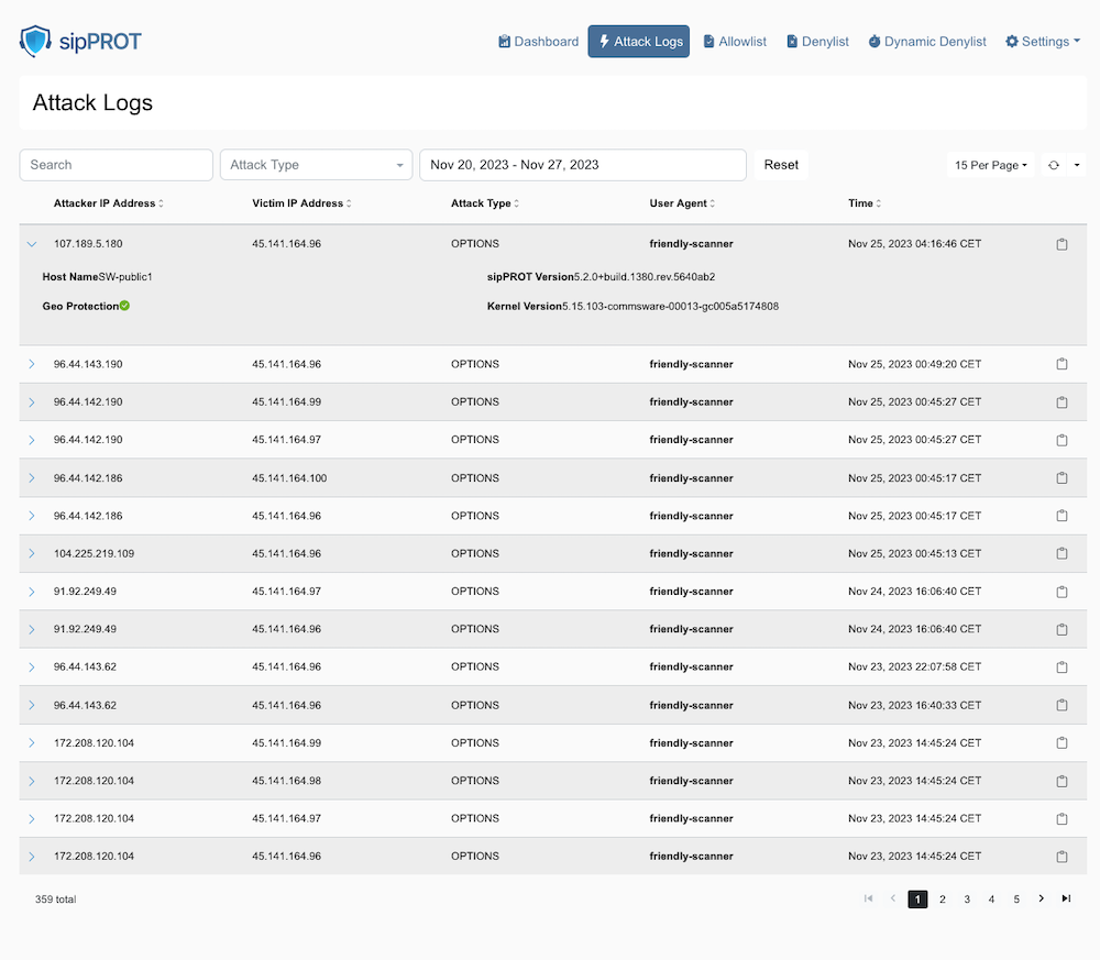
How to Use the sipPROT Attack logs page:
| Action | Description |
|---|---|
| Understanding the Interface: | Attack logs page displays a table of SIP (Session Initiation Protocol) attacks detected by sipPROT. The columns include Attacker IP Address, Victim IP Address, Attack Type, User Agent, and Time of attack. |
| Reviewing Attack Logs: | Scan through the list to review the recent attacks detected by sipPROT. Look at the 'Time' column to see when each attack occurred. The 'User Agent' column may give users insights into the type of tools used for the attack. If the user agent in the list is bold it will indicate that user agent is blocked explicitly in the sipPROT settings. |
| Filtering Logs: | Use the 'Search' bar to filter logs by specific criteria, like IP address or attack type. Users can select different types of attacks from the 'Attack Type' dropdown to narrow down the logs displayed.There are two type of attacks available to filter OPTIONS and REGISTER. |
| Inspecting Specific Attacks: | Click on the IP address of either the attacker or victim to possibly see more details about that particular entity (this functionality depends on sipPROT's features). |
| Managing Logs: | The date filter at the top allows adjustment of the log viewing range. Any applied filters can be cleared by clicking the Reset button. |
| Using Geo Protection: | If available, the 'Geo Protection' indicator can show if geo-blocking features are active or whether an attack was mitigated based on geographical rules. |
| Navigating Pages: | Use the navigation arrows or page numbers at the bottom to scroll through multiple pages of logs. |
| Adjusting View Settings: | Users can change how many logs they can see per page by adjusting the setting in the top right corner where it says '15 Per Page'. |
| Taking Action: | Based on the information in the logs, users might decide to update their firewall rules, add certain IP addresses to a blocklist, or take other security measures. |
¶ Allow/Deny Lists
The Allow/Deny lists offer a variety of management options, such as searching, exporting, importing, and deleting entries. Additionally, users can easily access more detailed information for each entry with a single click, offering valuable insights for more effective list management.
¶ Buttons

- Add (Mannualy add single IP record to the list)
- Export (export the whole list to a CSV file)
- Import (import the list from a CSV file)
- Delete (delete selected IP record)
¶ Search
- Search (Search the list by IP record or note)
- Country (Search IP records by country)
- Reset (Clear the country and reset the search)
¶ Display and Refresh Options
- Show per page (dropdown to select number of records displayed per parge)
- Refresh (The "Refresh" option in the allow list is a dropdown that allows users to set the refresh interval for the list. When a refresh interval is set, the list will automatically refresh at the specified interval. However, it's important to keep in mind that this action may clear any current selections in the list. )
At the bottom of the list, users can find:
- Number of selected/total records.
- Page numbers with selector.
¶ Note
Also for the convinience additional information regarding the specific IP can be found with a single click on the arrow on the beggining of the record to expand the additional information for the record, containing:
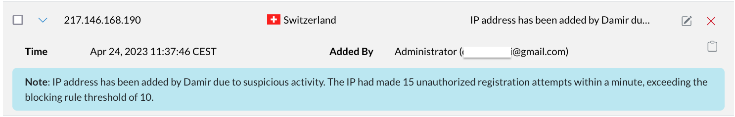
- Note: The note for the record if available.
- Added By: The user who added the record.
- Copy button: Copy the record data in the clipboard in json format.
   {
   "ip": "217.146.168.190",
   "note": "IP address has been added by Damir due to suspicious activity. The IP had made 15 unauthorized registration attempts within a minute, exceeding the blocking rule threshold of 10.",
   "time": 1682329066,
   "added_by": "Administrator (user@gmail.com)",
   "geo_data": {
      "country_code": "CH",
      "country_name": "Switzerland"
   }
   }
- Edit: Edit the record button.
- Delete: Delete the record button.
¶ Allowlist
The allowlist is a list of IP addresses that are allowed uninterrupted access to the system. This list can be manually populated via a form or uploaded using a CSV file. It is important to keep the allowlist up-to-date to ensure that legitimate users are not blocked from accessing the system. The allowlist provides an additional layer of security to the system and helps prevent unauthorized access.
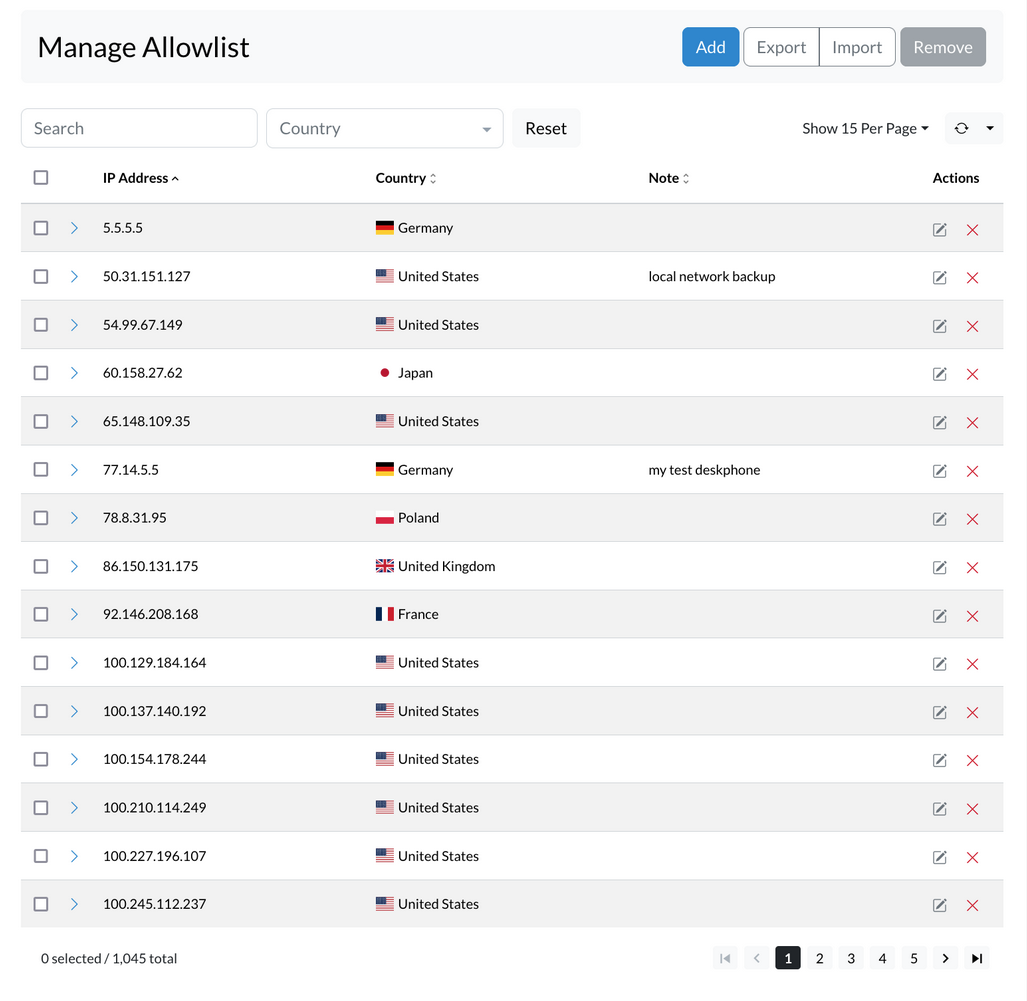
¶ ADD IP Records to Allowlist
To add an IP address to the Allowlist, follow these steps:
- Navigate to the Allowlist tab in sipPROT.
- Click the Add button.
- Enter the network or IP address in the designated input field.
- Optionally, add notes to provide context or reasons for adding the address.
- Click Add again to confirm and include the IP address in the Allowlist.
It's important to ensure that the entered IP address is accurate and valid. Once an IP address is added to the Allowlist, it will be allowed uninterrupted access to the system.
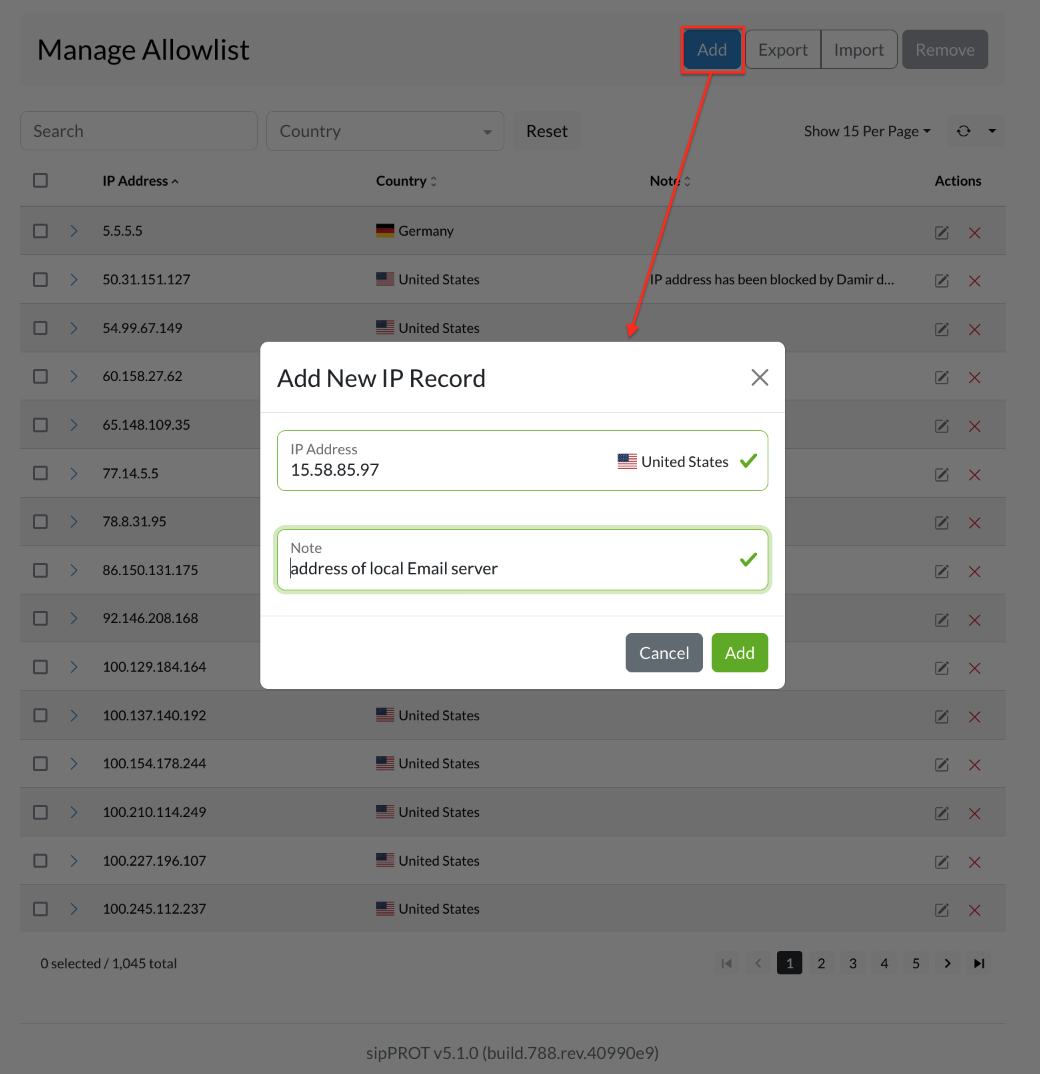
¶ IMPORT / EXPORT Multiple IP Records to Allowlist
To import multiple IP addresses into the Allowlist, use the Import CSV option in the upper right corner of the Allowlist IP Addresses tab. A CSV file containing the IP addresses to be added to the Allowlist is required.
The CSV file can be created by downloading the provided template file, which includes headers and examples to help get started. Open the file in a spreadsheet program like Microsoft Excel or Google Sheets, then add the IP addresses to allow access under the "IP_ADDRESS" column. An optional note can be added for each IP address in the "NOTE" column.
Example CSV file :
IP_ADDRESS,NOTE
192.168.x.x,"example note1"
77.14.x.x,"example note2"
Save the file as a CSV, ensuring it is in the correct format. Then, return to the Allowlist sipPROT tab in the system and click the "Upload" button. Select the CSV file created and click "Upload" again. The system will import the IP addresses from the file and add them to the Allowlist.
To export the list of IP addresses from the Allowlist, use the "Export CSV" option to download a file containing all IP addresses currently on the Allowlist.
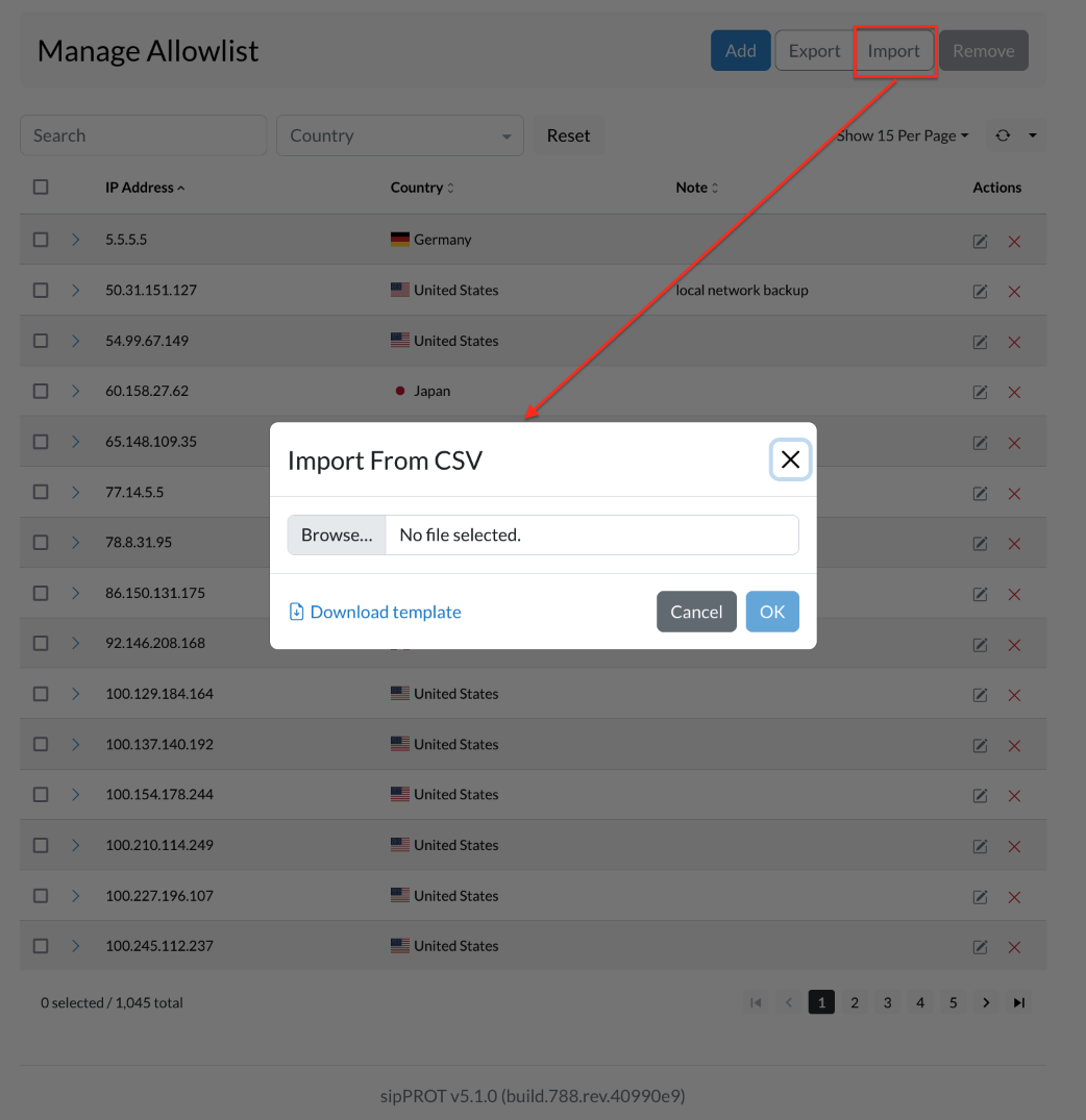
¶ Remove IP Address rom the List
IP addresses can be removed in two ways. To delete selected entries, mark the checkboxes next to the desired IPs and click Remove. A confirmation window will appear; select Yes to confirm the action.
To remove all entries, use the Select all option, then click Remove and confirm with Yes.
All changes are applied immediately. For bulk removal, a CSV file can be used. A template is available, including headers and sample data, to assist with formatting.
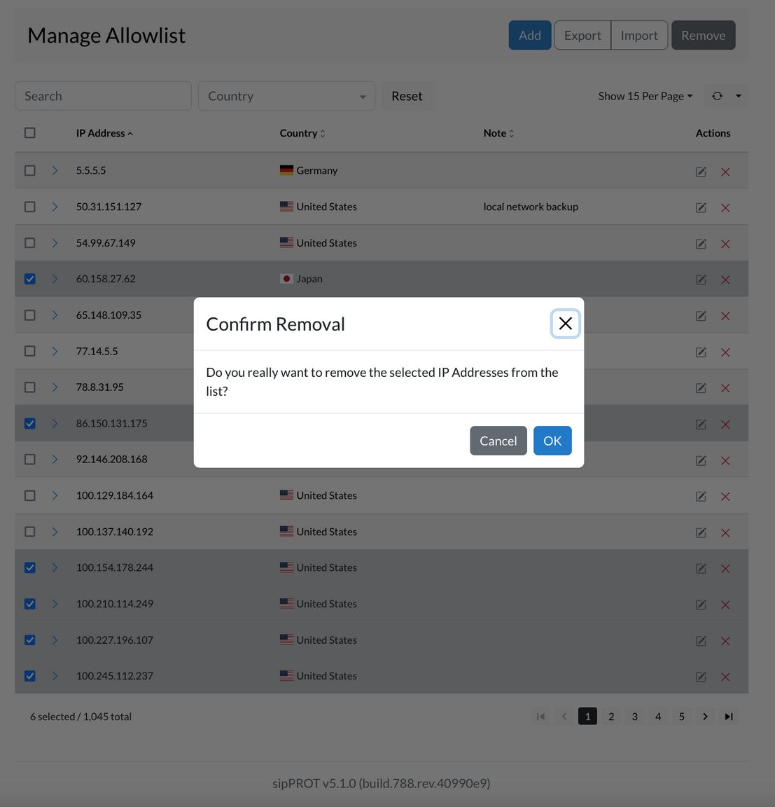
Please be noted that the Allowlist overrides all other lists. If an IP address appears in both the Allowlist and another list (like the Denylist), access will still be granted, and the conflicting entry in the other list will be ignored. This is especially useful when blocking an entire range—for example, a subnet like 192.168.50.0/24—but needing to permit a specific IP within that range, such as 192.168.50.15. By adding that IP to the Allowlist, it bypasses the broader block and retains access.
¶ Denylist
The Denylist is a collection of IP addresses that have restricted access to the system. This list can be populated manually by entering an IP address and an optional "note" through a GUI or by importing a list of IP addresses via a CSV file. Additionally, the Denylist can be dynamically populated with IP addresses from the Dynamic Denylist if they are identified as being associated with persistent attacks on the system.
IMPORTANT - The Allowlist has precedence over the Denylist. If an IP address is present in both the Allowlist and the Denylist, the IP address will be granted access to the system.
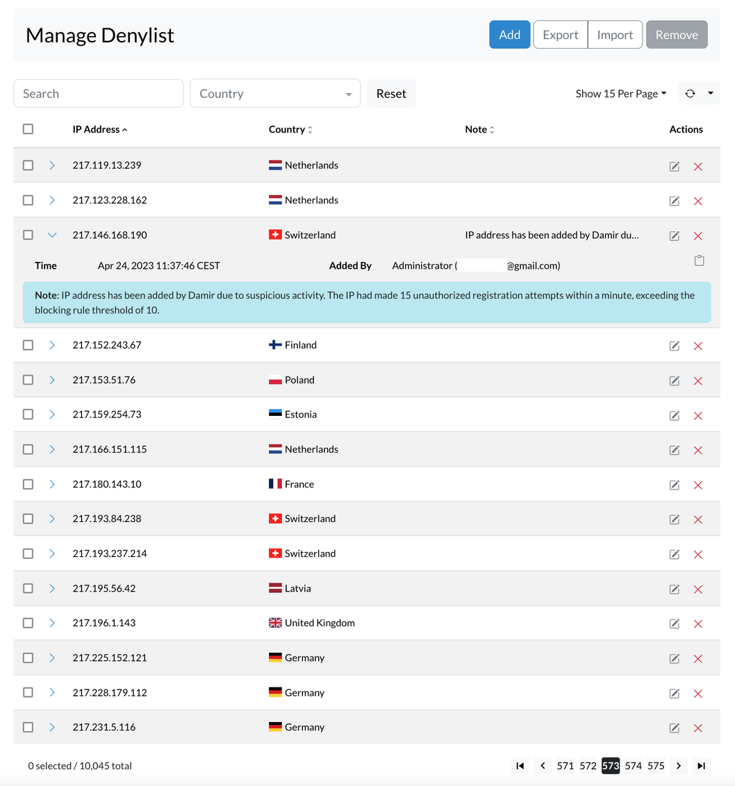
¶ ADD IP records to Denylist
To add an IP address to the Denylist, follow these steps:
- Open the Denylist tab in sipPROT.
- Click the Add button.
- Enter the network or IP address in the designated field.
- Optionally, provide notes to indicate the reason for adding the address.
- Click Add to confirm and include the IP address in the Denylist.
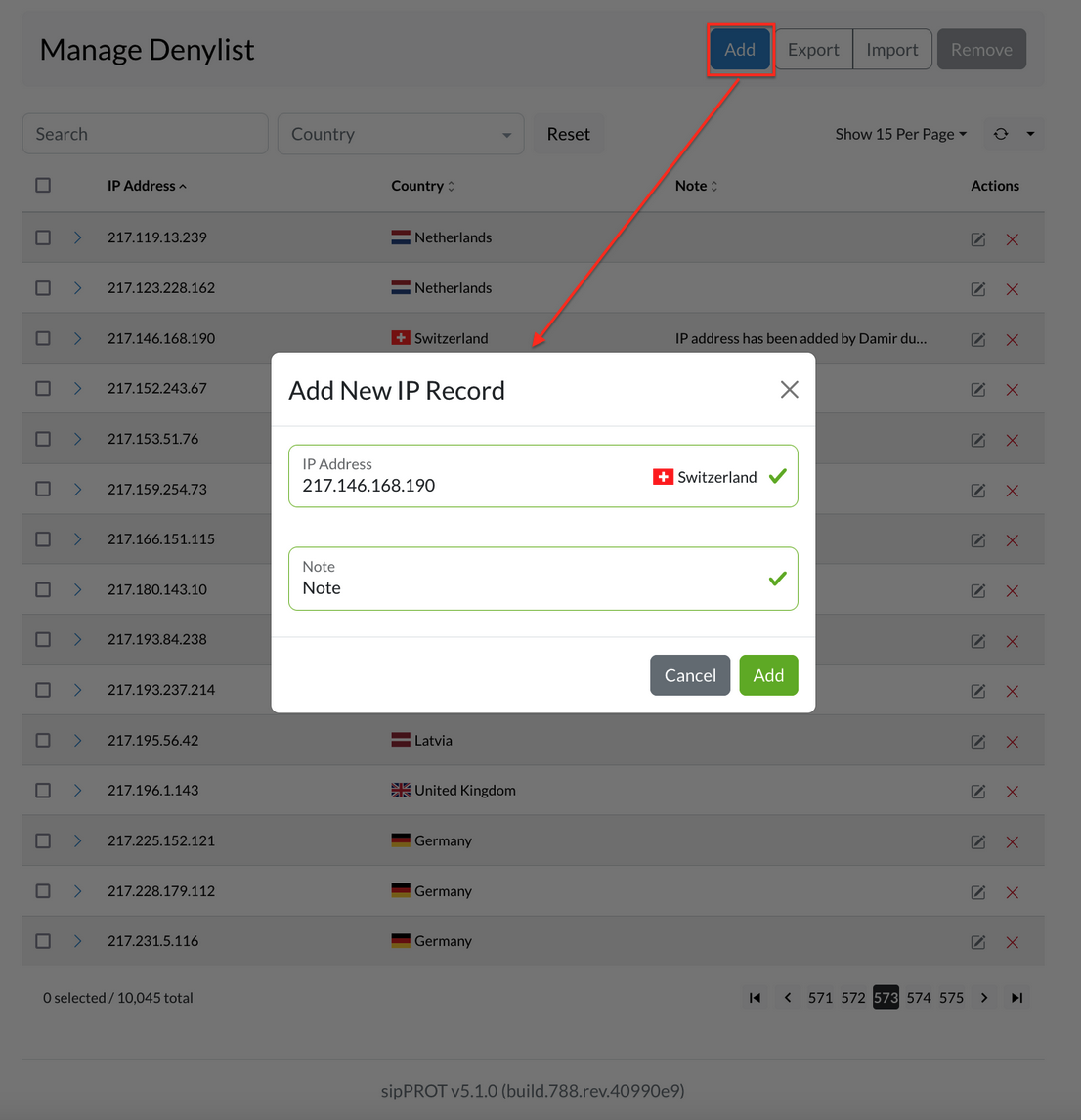
¶ IMPORT / EXPORT Multiple IP records to Denylist
Multiple IP addresses can be added to the Denylist using the Import CSV option found in the upper-right corner of the Denylist tab. This feature requires a CSV file containing the IPs to be added.
A downloadable template is available to help with formatting. It includes headers and example entries. After downloading, the file can be opened in a spreadsheet tool like Microsoft Excel or Google Sheets. IP addresses should be added under the IP_ADDRESS column, with an optional comment or description in the NOTE column.
Example CSV file :
IP_ADDRESS,NOTE
192.168.x.x,"example note1"
77.14.x.x,"example note2"
After editing, save the file in CSV format. Then return to the Denylist tab in sipPROT and click the Upload button. Select the prepared CSV file and confirm the action. The system will process the file and add all listed IP addresses to the Denylist.
To download the current list of denied IP addresses, use the Export CSV option. This will generate a file containing all entries currently in the Denylist.
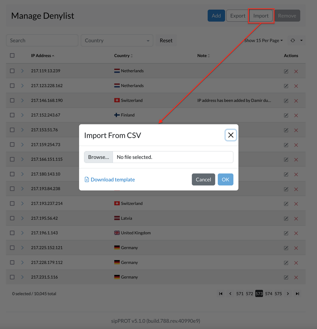
¶ Remove IP Address from the List
A network or IP address can be removed in two ways. Select one or more entries using the checkboxes next to them, then click the Remove button. A confirmation prompt will appear—choose Yes to confirm the removal. To delete all entries at once, use the Select all checkbox, then click Remove and confirm the action when prompted.
Changes take effect immediately. For removing many entries at once, a CSV file can be used for bulk updates. A template file with the correct format, headers, and sample entries is available to help with this process.
¶ Dynamic Denylist
The Dynamic Denylist shows IP addresses that have been automatically blocked after being flagged as sources of suspicious or malicious traffic. These entries are added without manual action, keeping the system protected in real time against ongoing threats. Each blocked IP is listed with details such as the scanner or user agent involved in the attempt, and the country of origin. This helps in analyzing the type and source of the attack for inspection or troubleshooting purposes.
Blocked IPs can be manually removed if needed, or left to expire on their own once the timeout period is reached.
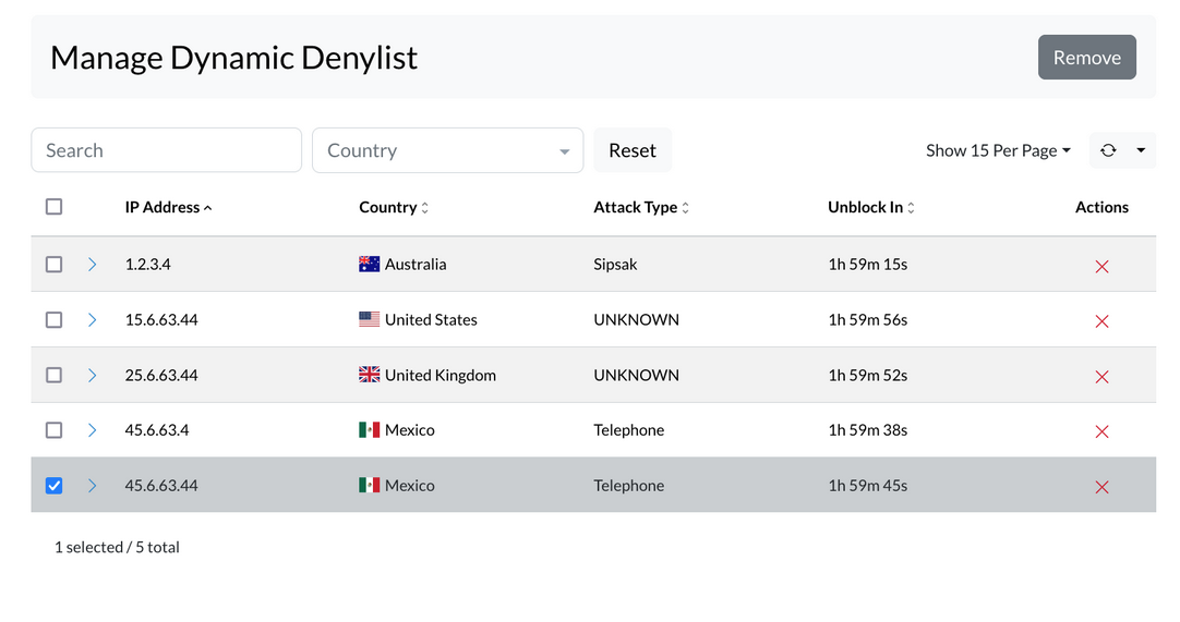
Dynamic deny is a security feature in sipPROT designed to automatically block IP addresses that exhibit malicious behavior against user's system. This feature operates based on a set of predefined rules established by the administrator. Here's a more detailed explanation:
| Field | Description |
|---|---|
| Dynamic Blocking: | When an IP address attempts an action that violates the rules set in sipPROT (like repeated failed login attempts, which could indicate a brute force attack), the dynamic deny feature is triggered. This results in the offending IP address being temporarily blocked. |
| Dynamic Block Time: | This is a crucial setting within the dynamic deny feature. It specifies the duration for which an IP address will be blocked once it violates the rules. For example, if the Dynamic Block Time is set to one hour, any IP address that breaks the rules will be blocked for an hour. |
| Behavior During the Block Period: | If the blocked IP address attempts another attack while it is still in the blocked state, the Dynamic Block Time is reset. This means the block duration starts over, and the IP remains blocked for another full hour from the time of the new attack. |
| Unblocking: | If the blocked IP address does not attempt any new attacks during the block period, it will be automatically unblocked once the Dynamic Block Time elapses. |
| Permanent blocking: | An IP address is added to the denylist if it persistently attacks and is repeatedly blocked by the dynamic deny feature. This is governed by the "Block Threshold" setting. For example, if an IP address commits more than 3 attacks within a specified time frame (as defined in settings), it will be permanently blocked, meaning it is moved to the denylist. This ensures that consistently malicious sources are dealt with more stringently. |
The dynamic deny feature in sipPROT acts as a proactive defense layer, automatically blocking IP addresses that show suspicious or harmful behavior. These temporary blocks are triggered by rules set by the administrator and help reduce the risk of repeated or ongoing attacks. Once the threat subsides, blocked IPs are automatically removed after a set timeout.
¶ sipPROT Hosts
To access the hosts page use the top navigation menu Settings > Hosts, or click directly on the dasboard, Health widget.
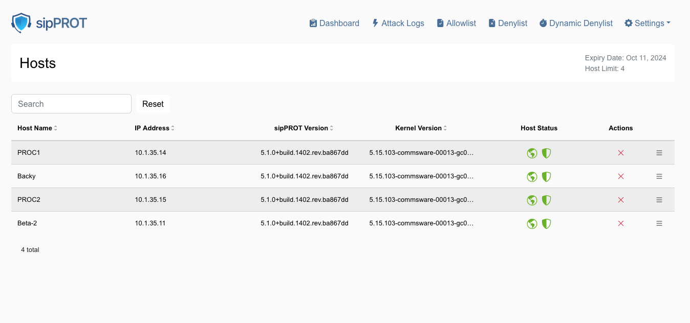
The sipPROT hosts page offers a comprehensive overview of various hosts. On this page, users can access detailed information about the status of the sipPROT service for each host. This includes:
| Feature | Description |
|---|---|
| Service Status Per Host | Displays the current operational status of the sipPROT service on individual hosts. A red shield icon indicates the service is not running and needs inspection. |
| License Information | Shows details about the sipPROT license, including its validity and the number of hosts it covers. |
| GEO Protection Status | Indicates whether geo-protection features are active and functioning correctly on each host. A red earth icon indicates the GEO service is unavailable and requires inspection. |
| sipPROT version | Displays the installed sipPROT version per host. |
| Host kernel version | Displays the kernel version installed on each host. |
| Host IP | Shows the IP address of each host. |
Additionally, this page provides functionality to remove hosts. Removing a host will temporarily disable the sipPROT service on that host until it is restarted. This feature is particularly useful in cases where the number of hosts exceeds the license limits. For example, backup hosts that typically do not run SIP services can be selectively unprotected to stay within the license limits.
¶ sipPROT Notifications
To access the notifications page in sipPROT use the top navigation menu Settings > Notifications.
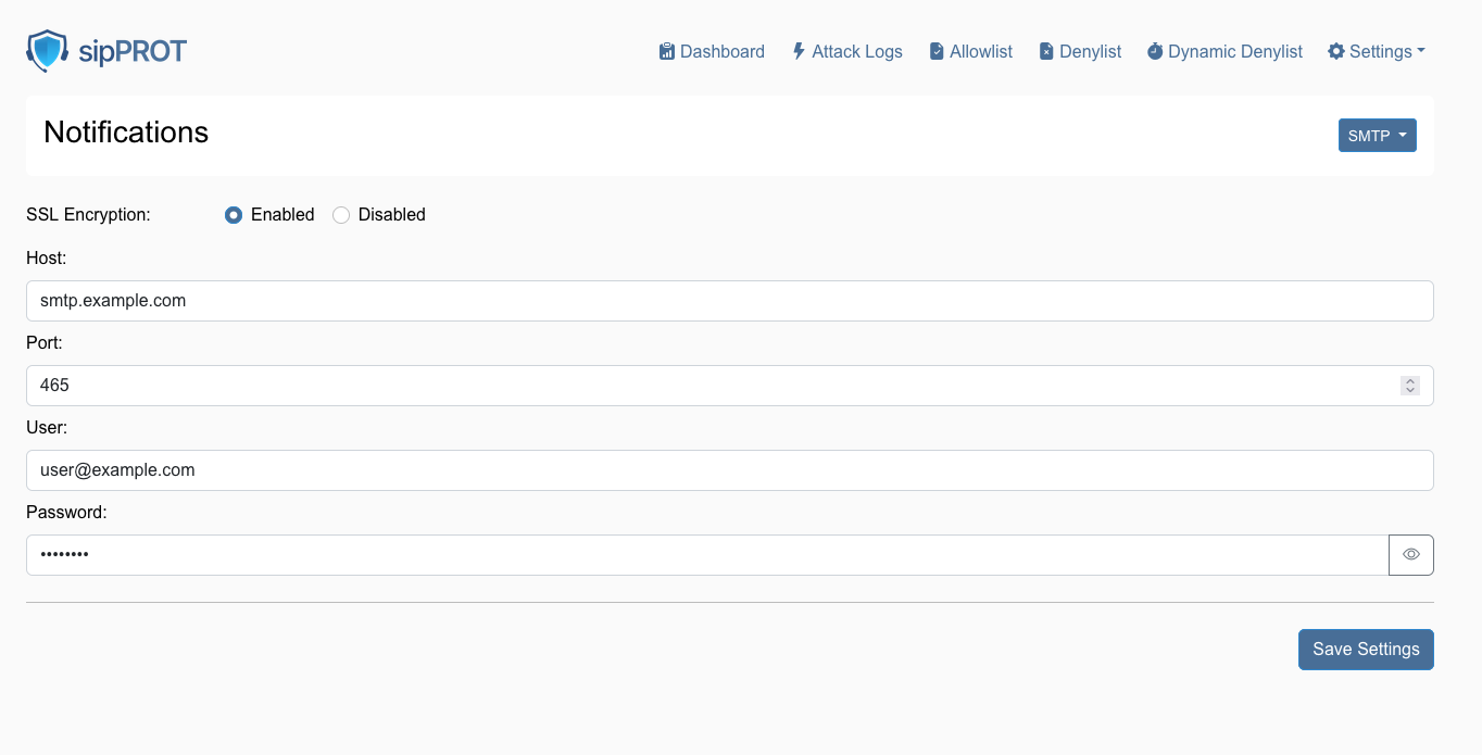
| Action | Description |
|---|---|
| Configure SSL Encryption: | Select the 'SSL Encryption' option and choose 'Enabled' to ensure that notification emails are sent using a secure connection. |
| Enter SMTP Details: | |
| Host: | Enter the SMTP server address for email provider, such as smtp.example.com. |
| Port: | Input the port number used by SMTP server. Commonly, this is 465 for SSL or 587 for TLS. |
| Enter User Credentials: | |
| User: | Input the full email address that will be used to send notifications, such as user@example.com. |
| Password: | Enter the password associated with the email account. Make sure to input this accurately. |
| Save Settings: | After ensuring all the information is correct, click the 'Save Settings' button to apply the changes. |
¶ sipPROT API Documentation
A new "API Documentation" button has been introduced in the GUI, providing users with direct access to a Swagger-enabled API documentation page. This page allows users to explore and test API endpoints in real time.
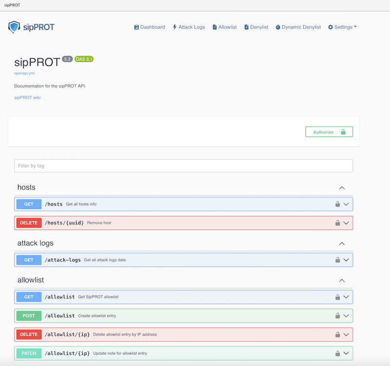
How to Use the API Documentation:
-
Accessing the Documentation:
- Click on the "API Documentation" button in the GUI. This will open a new browser tab with the Swagger interface displaying the available API endpoints.
-
Authentication Required:
- To execute API calls directly from the documentation, users need to generate an API Key for their user account.
-
Generating an API Key:
- Navigate to the user settings section in the GUI.
Create a new API key and copy it.
- Navigate to the user settings section in the GUI.
-
Using the API Key in Swagger:
- Go back to the Swagger interface.
- Locate the "Authorize" button or the input field for authentication.
- Paste the generated API key into the login prompt to authenticate requests.
-
Executing API Calls:
- Once authenticated, users can select an API endpoint, provide the required parameters, and execute the request directly from the Swagger interface.
¶ Working with sipPROT CLI
The new updated version of sipPROT comes with updated CLI commands and outputs. CLI autocomplete is added for sipPROT commands.
 # sipprot --help
NAME:
   sipPROT - CLI

USAGE:
   sipPROT [global options] command [command options] [arguments...]

VERSION:
   5.1.0+build.1445.rev.2accad6

COMMANDS:
   status, s        Prints number of IPs per list
   check-update, u  Check for updates
   version,         Print only the version
   list, l          Manages IP lists
   settings         To inspect settings
   help, h          Shows a list of commands or help for one command

GLOBAL OPTIONS:
   --config FILE  load configuration from FILE (default: "/opt/sipprot/conf/sipprot.conf")
   --log value    log URI e.g. stdout://, syslog:// or file:///var/log/sipprotd.log (default: "stdout://")
   --debug        include debug logs (default: false)
   --help, -h     show help
   --version, -v  print the version
¶ sipPROT Status
To get information about sipPROT status use the following command:
- sipprot status
This command will give the following information:
# sipprot status
+---------------------+------------+
|        LIST         | NUM OF IPS |
+---------------------+------------+
| Allow               |        493 |
+---------------------+------------+
| Deny                |        482 |
+---------------------+------------+
| Dynamic (temporary) |        100 |
+---------------------+------------+
To list detailed information use flags --all, --allow, --deny, --dynamic
Example:
# sipprot status -allow

Allowlist:
+-----------------+----------------+
|   IP ADDRESS    |    COUNTRY     |
+-----------------+----------------+
| 191.85.106.233  |   Argentina    |
+-----------------+----------------+
| 165.191.222.98  |   Australia    |
+-----------------+----------------+
|  175.35.61.159  |   Australia    |
+-----------------+----------------+
|  83.164.34.163  |    Austria     |
+-----------------+----------------+
|  178.127.91.72  |    Belarus     |
+-----------------+----------------+
| 178.116.223.166 |    Belgium     |
+-----------------+----------------+
| 109.140.180.239 |    Belgium     |
+-----------------+----------------+
Print sipPROT version information:
# sipprot version
sipPROT:  5.1.0+build.777.rev.5ad785a
Additional quick check, if the provided IP is in any of the following: allowlist, denylist, dynamic denylist.
Example:
# sipprot list check 83.221.171.193
IP address '83.221.171.193' found in Allowlist
IP address '83.221.171.193' found in Denylist
If an IP address is in the "List of IPs in the allow list," that IP will not be blocked by sipPROT.
If an IP address is in the "List of IPs blocked by the deny list," IP will be blocked regardless of whether an attack is coming from that IP.
"The information shown in the screenshots on this wiki such as IP addresses, hostnames, email addresses, and service versions are placeholders used for demonstration purposes within the sipPROT interface. They are not indicative of actual threats or real-world configuration and should not be treated as such."
¶ Settings
The Settings section serves as the central hub for configuring and managing key infrastructure components within SERVERware. It is divided into two primary views: Storage and Networking, each offering specific tools and information to optimize system performance and connectivity.
¶ Storage
This view offers a clear overview of the system's storage configuration. Administrators can monitor each storage host's capacity, view pool names, and track disk usage. Additionally, the page provides access to the associated iSCSI IP address for each host.
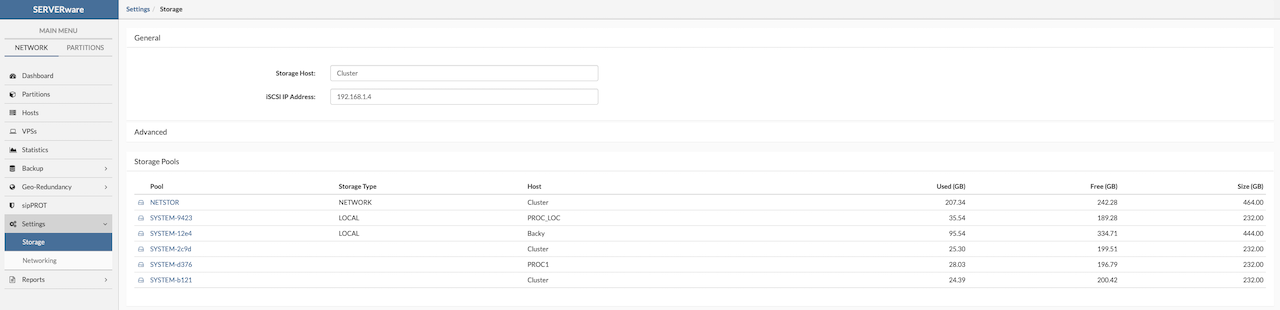
¶ Networking
¶ Logical Subnets
The Networking view in SERVERware allows administrators to add, configure, and remove logical subnets used across the platform. These subnets support various network roles, including LAN, SAN, RAN, and MAN, each serving a specific function within the infrastructure to ensure reliable communication, data access, and system management.
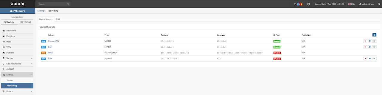
Local Area Network (LAN):
- Enables communication between the SERVERware management system and virtual servers (VPSs). The LAN network supports both IPv4 and IPv6, allowing administrators to define custom IP ranges for VPS connectivity.
Management Area Network (MAN):
- The MAN is an internal IPv6 service network with a dedicated address range (e.g., feb1:a0fe:d4d6:4dbc::/64). It is used exclusively by the system and is not accessible to administrators or users.
Storage Area Network (SAN):
- A Storage Area Network enables processing hosts to access and use storage provided by storage hosts."
Replication Area Network (RAN):
A Replication Area Network is used to replicate data between storage hosts, ensuring backups, redundancy, and disaster recovery.
¶ Adding an IPv4 Range
To add and configure a new network subnet in SERVERware, follow these steps carefully:
-
Users should navigate to the Networking section and select Add Subnet to begin creating a new logical subnet. A descriptive name for the subnet, such as LAN2, should be entered to help identify its role within the network.
-
Next, the appropriate subnet type should be selected from the available options—for example, MIXED—depending on how the subnet will be used.
-
If the subnet is intended for VPS networking, the box labeled Use this subnet for VPS networking must be checked. The name of the bridge interface that will connect VPSs to this subnet should then be provided. It is essential that the bridge interface with this exact name is preconfigured on all hosts in the SERVERware cluster using the netsetup CLI tool to ensure consistent network connectivity across the cluster.
-
By default, the configuration window opens on the IPv4 tab. Here, the subnet's base IP address (e.g., 192.0.2.0), subnet mask (e.g., 255.255.255.0), and gateway IP address (e.g., 192.0.2.1) should be entered. After completing the required fields, clicking Add will save the new subnet configuration.

¶ Adding an IPv6 Range
The following steps outline the procedure users should follow to add and configure an IPv6 subnet within SERVERware:
-
Navigate to the Networking section and select Add Subnet.
-
Switch to the IPv6 (Beta) tab:
-
Enter the Routing Prefix (e.g., fd00:a12c:12a4:: ).
-
Specify the Prefix Length (e.g., 64).
-
Enter the Gateway address (e.g., fd00:a12c:12a4::1).
- Click Add to save the configuration.
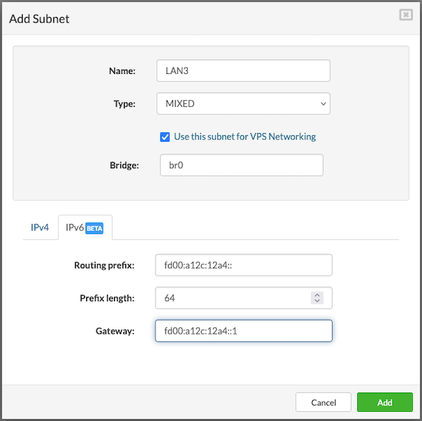
¶ Removing Logical Subnet
To remove a logical subnet, users should navigate to the Networking view in the Settings menu, click Remove next to the desired subnet, and confirm the action by clicking Yes; the subnet will then be removed from the list.
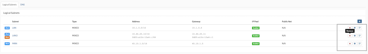
¶ Extending IP Address Pool
To configure an existing logical subnet, users should navigate to the Networking view within the Settings menu. Next, locate the logical subnet that requires configuration and click Configure. This action will open the Configure Subnet dialog, where users can modify the subnet settings as needed.
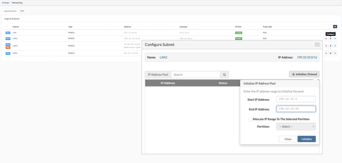
- Enter the IP address range to extend the pool and click Save to apply the changes.
- Next, click Allocate IP Range To The Selected Partition and choose the partition to assign the new IP range.
- Once complete, click Close to exit the Configure Subnet dialog.
¶ Removing IP Address from the Pool
In the Settings menu, navigate to the Networking view, select the logical subnet to be configured, and click Configure. The Configure Subnet dialog will appear. To remove an IP address from the pool, click the Release button next to the desired IP address in the list.
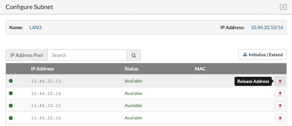
When the confirmation dialog appears, click Yes to release the IP address.
After making the necessary changes, click Close to exit the Configure Subnet dialog.
¶ Create Virtual Network Interface (virtnet)
Virtual networking lets multiple virtual machines (VPS) talk to each other, similar to how physical networks connect computers with cables and hardware. But instead of relying on physical wires, virtual networking uses software to link devices, making it easier to set up and manage. It works by creating virtual versions of things like switches and network cards, which helps data move around smoothly and makes changing the network simpler.
This gives network administrators more efficient ways to connect VPSs and greater flexibility to tailor the network for specific needs and applications. It also allows workloads to move across the network without affecting service quality, security, or availability.
Create a virtnet
To create a new virtual interface, users must first add a new virtual network.
- Navigate to Settings > Networking from the main menu. In the upper right corner, select the "+" button to open a popup with the network interface parameters.
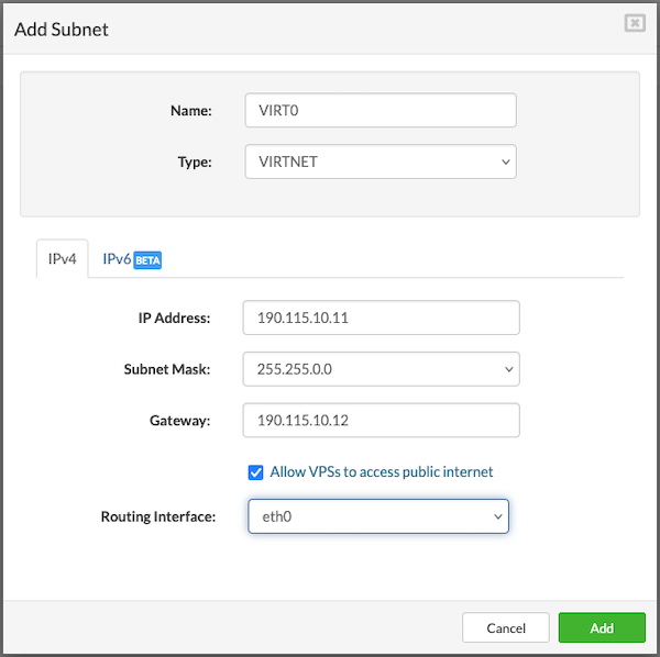
Enter the required values as follows:
-
Name: Provide a name for the new network (limited to 15 characters).
-
Type: Select VIRTNET from the dropdown menu.
-
IP Address: Enter the network address range.
Example for IPv4: 192.0.2.0 -
Subnet Mask: Specify the subnet mask for the selected network.
Example for IPv4: 255.255.0.0
-
Gateway: Enter the gateway address, such as 192.0.2.1. This address will be assigned to the SERVERware CONTROLLER, which functions as the gateway/router for the virtual networks.
Note: The Bridge option is automatically added by the server, and the corresponding GUI options will be grayed out.
-
If IPv6 is required, users should populate the IPv6 tab using the format and examples provided above.
-
After all fields are completed, users should press the Add button to finish creating the new virtual network.
-
Finally, IP addresses must be added to the IP pool within the newly created network, following the procedure described earlier.
¶ DNS Zones
The DNS plugin allows the SERVERware Controller to act as an authoritative DNS server for partition-based domain zones. It uses the SERVERware database to resolve VPS addresses, making DNS management simpler and more efficient.
¶ How It Works?
When a domain zone like stalone.techcorp.com is assigned to SERVERware, it can resolve host and VPS IP addresses based on their names. For example, a VPS named pbx1 would be reachable at pbx1.stalone.techcorp.com.
The plugin responds with either a public or private IP address depending on where the DNS request comes from. This helps with both internal and external access without needing different setups.
¶ Benefits
-
Automatic DNS Updates
If a VPS changes its IP or moves to another network, it remains accessible by name. No manual DNS updates are needed since SERVERware handles it automatically.
-
Service Discovery Support
The plugin supports SRV records, which can be used for service discovery. This is helpful for providers offering multiple services—just forward DNS requests to SERVERware and it handles the rest.
-
Real-Time Sync with PBXware
It's possible to deploy public DNS servers through PBXware's provisioning feature and keep them in sync with SERVERware. This avoids issues with third-party DNS caching and ensures changes are reflected immediately.
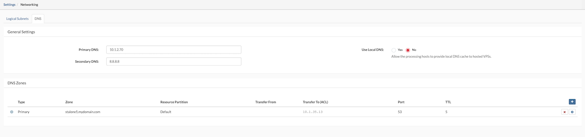
¶ Add New DNS Zone
To configure a DNS zone, navigate to Networking > DNS and follow the steps below:
- Click the Add New Zone button.

-
Type: Select the server role from the dropdown menu — either Primary or Secondary.
-
Name: Enter the name of the DNS zone, such as server1.mydomain.xyz. This will be the domain name used for DNS resolution.
-
Domain: Choose the domain to which the DNS zone will be limited. Selecting a domain from the dropdown restricts the zone to that SERVERware domain. If no selection is made, the zone will apply to all available domains.
-
Port: This is set to 53 by default, which is the standard port for DNS lookups. It should only be changed if specifically required by the network administrator.
-
TTL (Time to Live): Defines how long DNS resolvers should cache the zone information before requesting updated data. A higher TTL reduces DNS queries but delays updates, while a lower TTL allows for faster updates but increases traffic.
-
Transfer From: Enter the IP address of the primary server in the DNS zone. This field is only enabled when the zone type is set to Secondary.
-
Transfer To (ACL): Specify the IP addresses of the secondary servers allowed to receive zone data. This controls zone transfer permissions.
-Collect Metrics: Enable or disable metric collection for a selected DNS zone.
Once all fields are completed, click the Save button. The DNS zone will be created and ready for use.
Default DNS on all VPSs will be always set to CONTROLLER IP
¶ Test DNS Zone
To test newly added DNS zone users can use the dig command from the CLI to resolve the IP address from the VPS.
- Open the terminal and issue the next command:
~$ dig @< IP of SERVERware CONTROLLER > < name of the VPS >.mydomain.xyz
Example:
~$ dig @10.1.35.63 PBXware60.mydomain.xyz
 ; <<>> DiG 9.11.3-1ubuntu1.14-Ubuntu <<>> @10.1.35.63 PBXware60.mydomain.xyz
 ; (1 server found)
 ;; global options: +cmd
 ;; Got answer:
 ;; ->>HEADER<<- opcode: QUERY, status: NOERROR, id: 16840
 ;; flags: qr aa rd; QUERY: 1, ANSWER: 1, AUTHORITY: 0, ADDITIONAL: 1
 ;; WARNING: recursion requested but not available

 ;; OPT PSEUDOSECTION:
 ; EDNS: version: 0, flags:; udp: 4096
 ; COOKIE: 8962e1899e70b4bb (echoed)
 ;; QUESTION SECTION:
 ;PBXware60.mydomain.xyz.		IN	A

 ;; ANSWER SECTION:
 pbxware60.mydomain.xyz.	5	IN	A	10.1.35.70

 ;; Query time: 36 msec
 ;; SERVER: 10.1.35.63#53(10.1.35.63)
 ;; WHEN: Mon Apr 19 10:16:42 CEST 2021
 ;; MSG SIZE  rcvd: 101
¶ Reports
The Reports menu provides access to important system activity and monitoring tools. It expands into three key sections: System Logs, Alarm Logs, and User Sessions.
¶ System Logs
System Logs keep a record of all events that take place in SERVERware. They include general system activity, management actions, and are helpful for troubleshooting and analysis. Logs can be filtered to quickly find specific events.
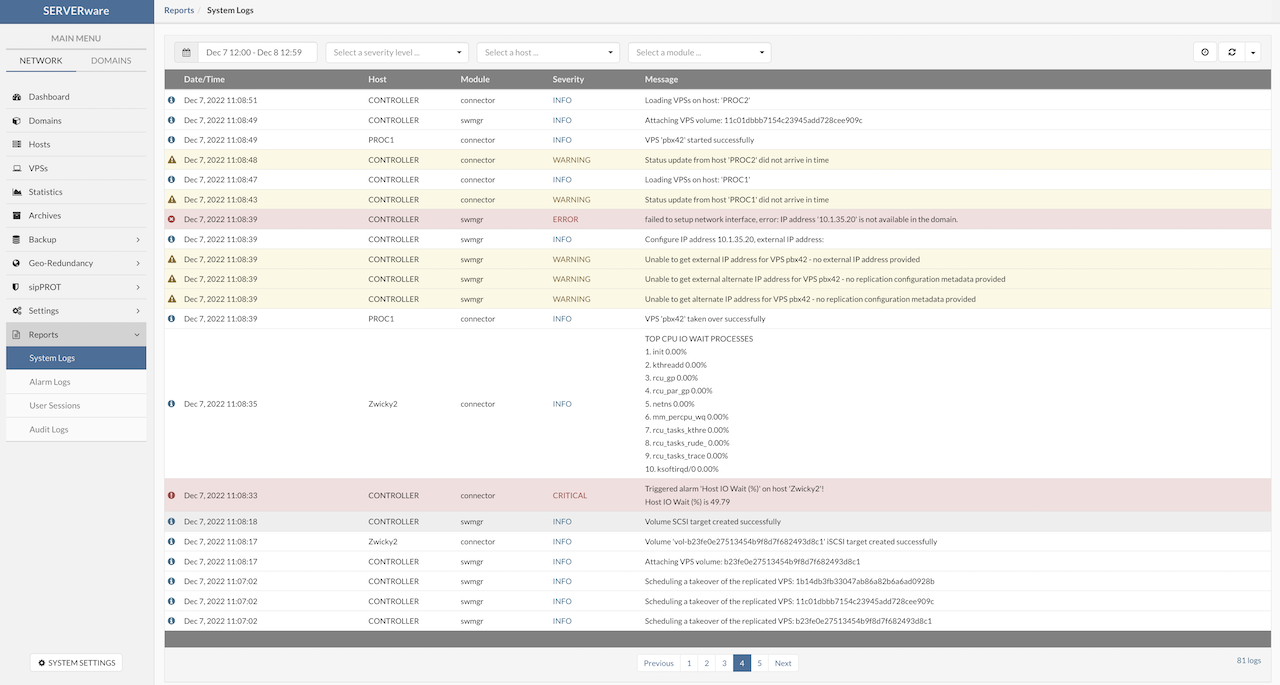
¶ Alarm logs
All triggered alarms are recorded in the Alarm Log. This log can also be used for troubleshooting and analysis. A filter is available to help display specific entries more easily.
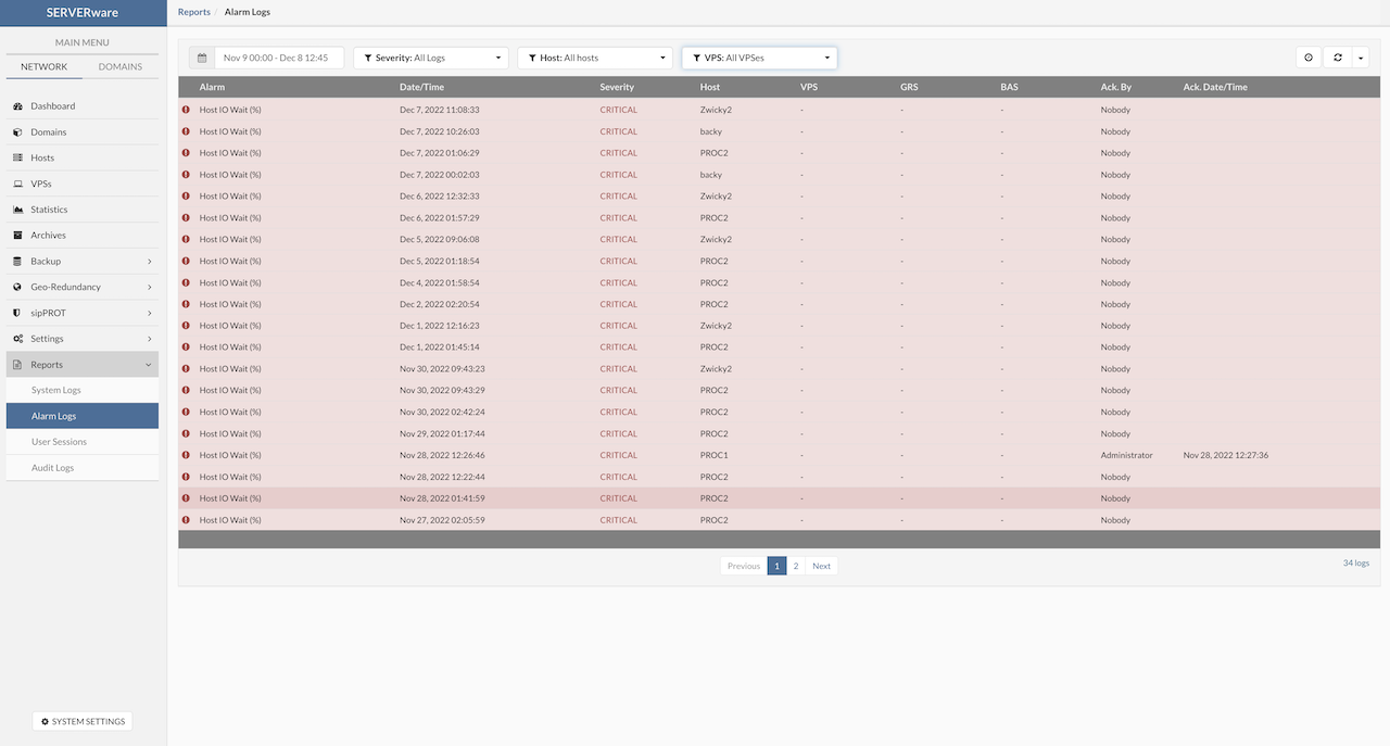
¶ User Sessions
The User Sessions view shows both active connections to the SERVERware GUI and a history of past sessions. It provides details such as the username, connection start and end times, IP address, and user agent, helping administrators monitor access and activity.
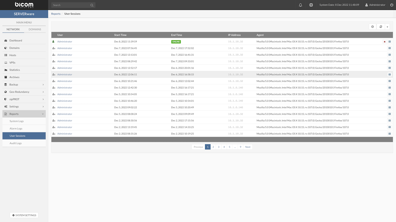
¶ Audit Logs
Audit logs are a record of actions that have been performed within a SERVERware. These logs typically include information about who performed the action, when the action was performed, and what the action was. Audit logs can be used to track changes made to a SERVERware, as well as to detect and investigate potential security incidents. In many cases, audit logs are considered an important tool for maintaining the security and integrity of a system, as they can provide valuable information for auditors and SERVERware administrators.
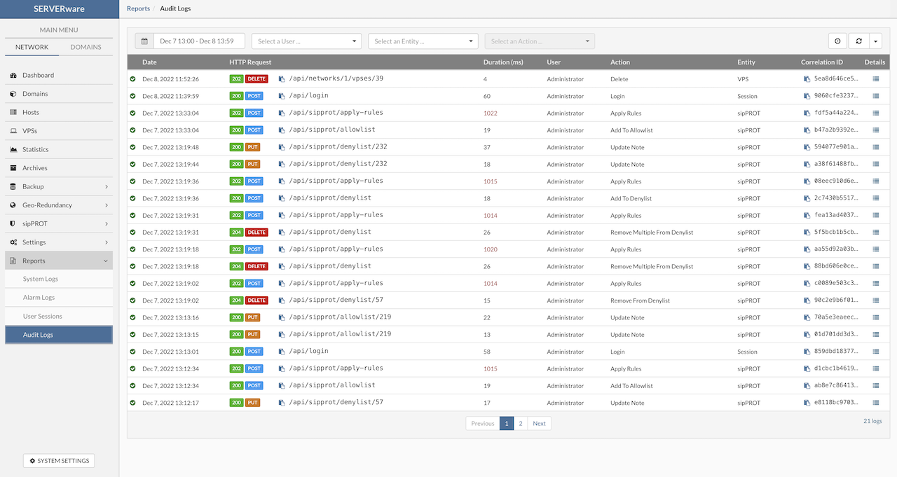
The filter is implemented so it can help SERVERware administrators to easier search and analyse Audit logs. By clicking on Details popup will appear with additional details about the action.
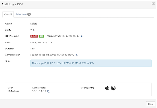
All sub-actions are previewed on the Subaction tab.
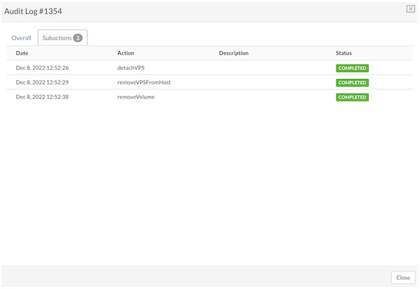
¶ System Settings
The System Settings section within SERVERware provides administrators with a centralized location to configure and manage core system parameters. This includes everything from network configurations and storage management to security settings and user permissions. By customizing these settings, users can tailor SERVERware to meet the specific needs of their environment, ensuring optimal performance, reliability, and security.
¶ Administrators
The Administrators menu provides tools for managing SERVERware GUI administrators. From this section, authorized users can create new administrators, edit existing administrator accounts, and remove administrators who no longer require access. This functionality allows for granular control over who has administrative rights within the SERVERware environment, ensuring that only trusted personnel can modify system settings, manage resources, and perform critical tasks.
Administrators can assign specific roles and permissions to ensure that each user has the appropriate level of access based on their responsibilities, which enhances security and maintains a controlled environment.
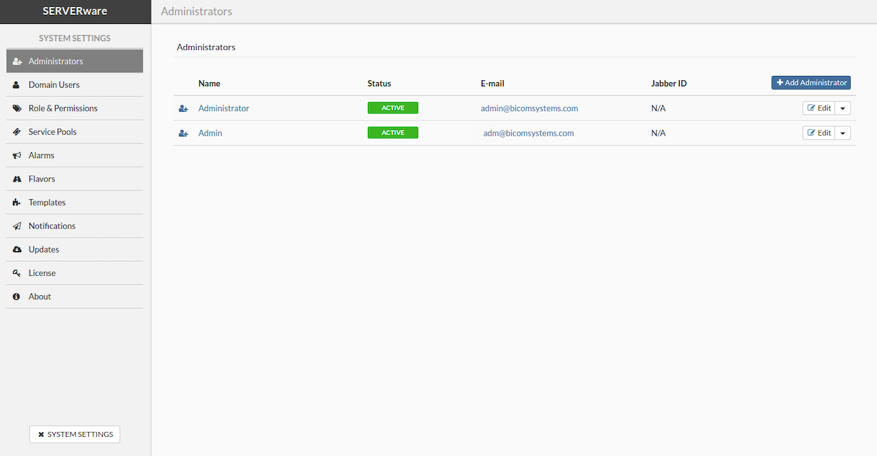
¶ Adding Administrator Account
To add an administrator account, navigate to the Administrators view and click the Add Administrator button. In the Add User dialog, select the user role, set the account status, and enter the administrator's personal information. After completing the details, click Add to create the new administrator account.
¶ Removing Administrator Account
To remove an administrator account, go to the Administrators menu and click the Edit button on the right side. From the dropdown menu, select Remove next to the account that needs to be deleted. A confirmation dialog will appear, and after confirming by clicking Yes, the administrator account will be removed from the list.
¶ Demoting Administrator Account to User Account
To demote an administrator account to a user account, navigate to the Administrators view and locate the Edit button. From the dropdown menu next to the administrator to be demoted, select Downgrade. A confirmation dialog will appear, and after clicking Yes, the account will be removed from the list of administrators and moved to the list of Partition Users.
¶ Partition Users
The Partition Users menu allows administrators to create, edit, and remove user accounts within the SERVERware GUI. It also provides the ability to assign roles and permissions to each user, ensuring that access levels are aligned with their responsibilities.
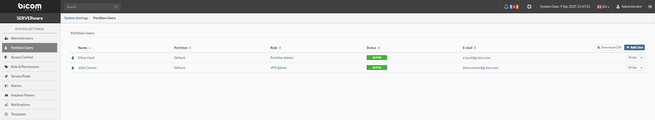
¶ Adding User Account
To add a user account, navigate to the Partition Users view and click Add User. The Add User dialog will appear, where the User Role can be selected, the Status set, and personal user information entered. Click Add to create the user account.
¶ Removing User Account
To remove a user account, in the Partition Users view, select Remove User from the Edit dropdown menu next to the user to be removed. A confirmation dialog will appear; click Yes to remove the user from the list.
¶ Promoting User Account to Administrator Account
To promote a user account to an administrator account, in the Partition Users view, select Upgrade from the Edis dropdown menu next to the user to be promoted. A confirmation dialog will appear; click Yes to move the user to the Administrators list.
¶ Access Control
Access control is a key feature for managing access to SERVERware Administration. This menu provides options for handling Blocked IPs, Allowed IPs, and configuring automatic lockouts after multiple failed login attempts. It allows administrators to set rules for who can access the system and helps enhance security by restricting unauthorized access attempts.
¶ Login Lockout
Configure the limit for the allowed failed login attempts. User IP will be blocked after the specified number of failed attempts within the specified retry time period in minutes.
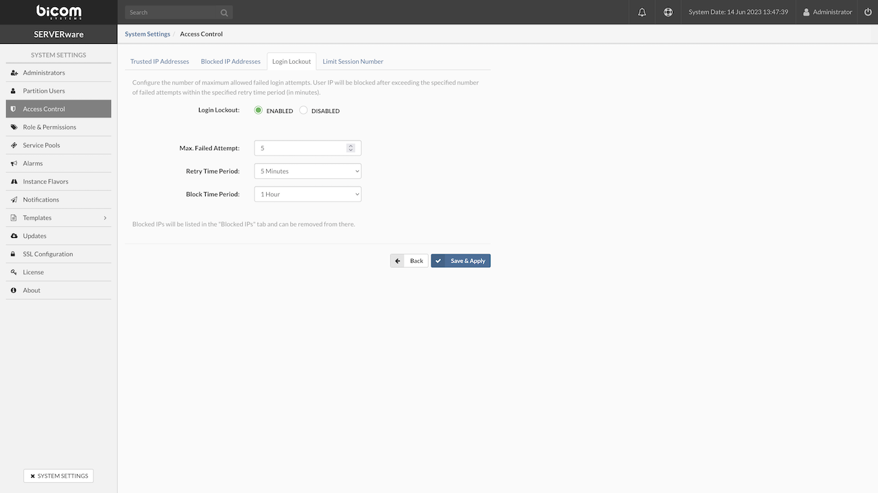
- Login Lockout: Enable or disable the login lockout feature.
- Max. Failed Attempts: Set the maximum number of failed login attempts allowed within a specified time period before the user account is blocked.
- Retry Time Period: Specify the time window within which failed login attempts are counted. Available options are 1 min, 5 min, 10 min, 30 min, and 60 min.
- Block Time Period: Define the duration for which the restricted user will be denied access after exceeding the allowed number of failed attempts.
If all conditions are met, the user account will be blocked after reaching the specified number of failed attempts within the defined time period, and the IP address will be added to the Blocked IP Addresses list.
¶ Blocked IP Addresses
The Blocked IP Addresses list contains IP addresses that have been temporarily restricted due to multiple failed login attempts or other access control violations. These IPs are denied access to SERVERware for the duration specified in the Block Time Period settings.
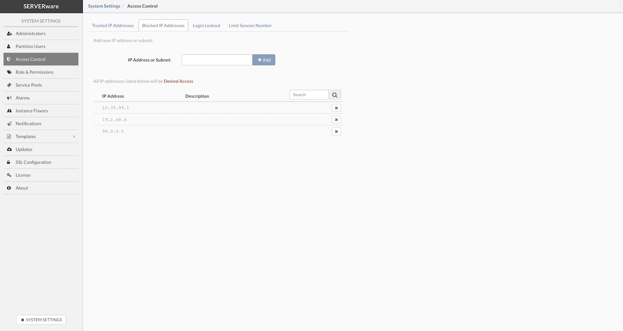
- IP Address or Subnet: To block access for a specific IP address, type the address in the input field and click the + Add button.
- To remove an address from the blocked list, click the X mark button next to the blocked IP address in the list.
¶ Trusted IP Addresses
The Trusted IP Addresses list allows administrators to specify IP addresses or subnets that are considered safe and exempt from certain security restrictions, such as login lockouts or access control filters. Adding an IP to this list ensures that traffic from these addresses is trusted and will not be blocked or limited by automatic security measures.
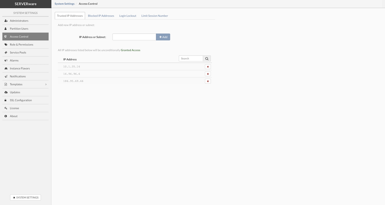
- IP Address or Subnet: To grant access for a specific IP address, type the address in the input field and click the + Add button.
- To remove an address from the granted list, click the X mark button next to the granted IP address in the list.
¶ Limit Session Number
Configure the number of maximum concurrent sessions. When enabled, attempts to connect beyond the maximum will be rejected. For example, if the session limit is 3, only 3 users can be connected simultaneously. Every next user login attempt will be rejected.
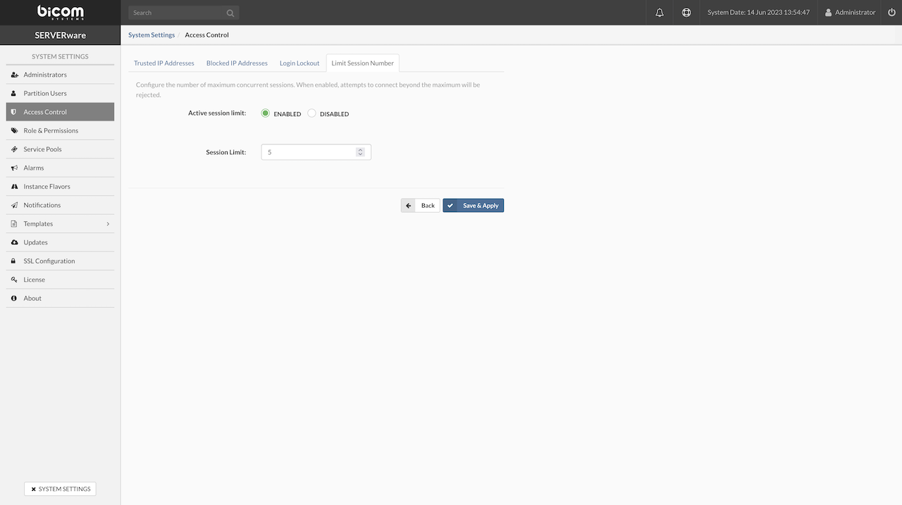
¶ Role & Permissions
Use the Role & Permissions view to add, edit, or remove roles and permissions that can be assigned to SERVERware GUI users. This allows administrators to define access levels and control what actions users can perform within the system.
¶ Adding Role
To add a role, follow these steps:
-
In the Role & Permissions view, click Add Role. The Add Role dialog will appear. Enter the role name, description, and configure the necessary permissions.
-
Click Add to create the role.
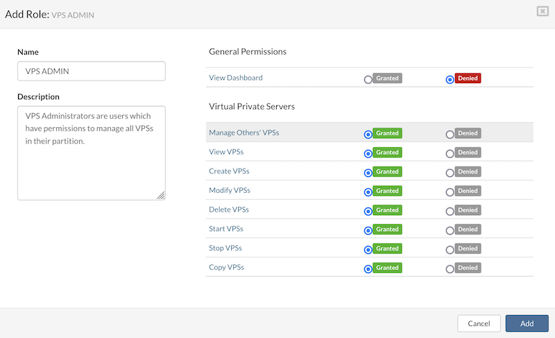
¶ Removing Role
To remove a role, follow these steps:
- In the Role & Permissions view, select Remove Role from the dropdown menu next to the role to be removed. A confirmation dialog will appear.
- Click Yes to remove the role from the list.
¶ Service Pools
The Service Pools tab provides functionality for managing service pools within SERVERware.
¶ Adding Service Pool
To add a new service pool, follow these steps:
- In the Service Pools view, click Add Service Pool.
- Enter a Name for the pool, select the appropriate Service Type, and click Save to create the new service pool.
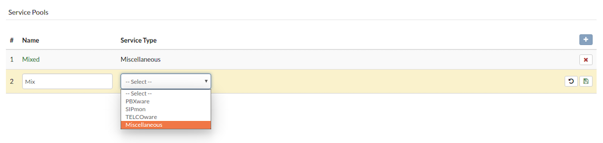
¶ Removing Service Pool
To remove a service pool, follow these steps:
- In the Service Pools view, click Remove Service Pool next to the service pool to be removed. A confirmation dialog will appear.
- Click Yes to remove the service pool from the list.
¶ Alarms
The Alarms view is used to set up and configure various alarms within SERVERware. These alarms can be tailored to monitor specific conditions and trigger notifications when those conditions are met, ensuring administrators are alerted to critical events or issues in the system.
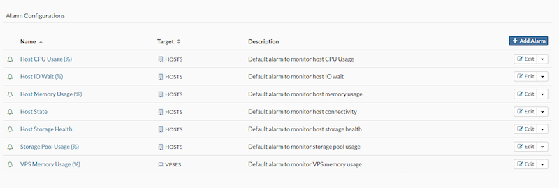
¶ Adding Alarm
To add an alarm, follow these steps:
-
In the Alarms view, click Add Alarm. The Configure New Alarm dialog will appear. Select the alarm state, specify the monitoring target, enter a name and description, then click Next.
-
In the Triggers tab, choose the trigger and operator, then set the warning and critical conditions.
-
Afterward, click Save Trigger and then click Next to complete the process.
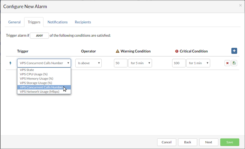
In the Notifications tab, configure the notifications for individual alarm state changes by selecting Notify and choosing the delivery methods (e.g., email, SMS, etc.). Once all notification settings are configured, click Next to proceed.
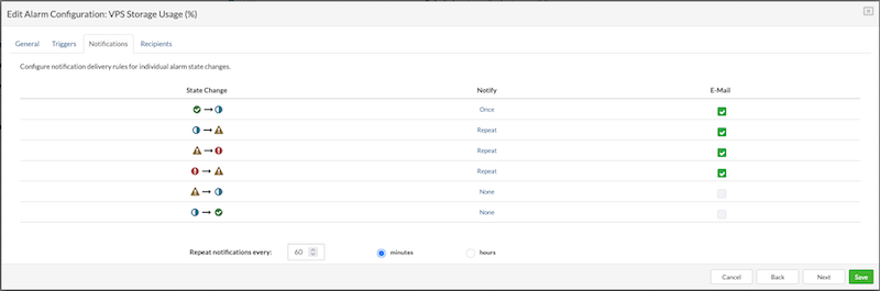
In the Recipients tab, select the groups that will receive the notifications for the alarm. Once the recipients are chosen, click Save to add the new alarm.
¶ Removing Alarm
To remove an alarm, follow these steps:
- In the Alarms view, select Remove Alarm from the dropdown menu next to the desired alarm configuration. A confirmation dialog will appear.
- Click Yes to confirm. The alarm will then be removed from the list.
¶ Flavors
Under the Flavors menu, administrators can add, edit, and remove Virtual Server Flavors. A flavor is essentially a preconfigured set of hardware resources, such as CPU, RAM, and storage, that can be assigned to a Virtual Private Server (VPS) during its creation. This allows for quick and consistent deployment of VPSs with specific resource requirements, optimizing resource allocation and simplifying management.
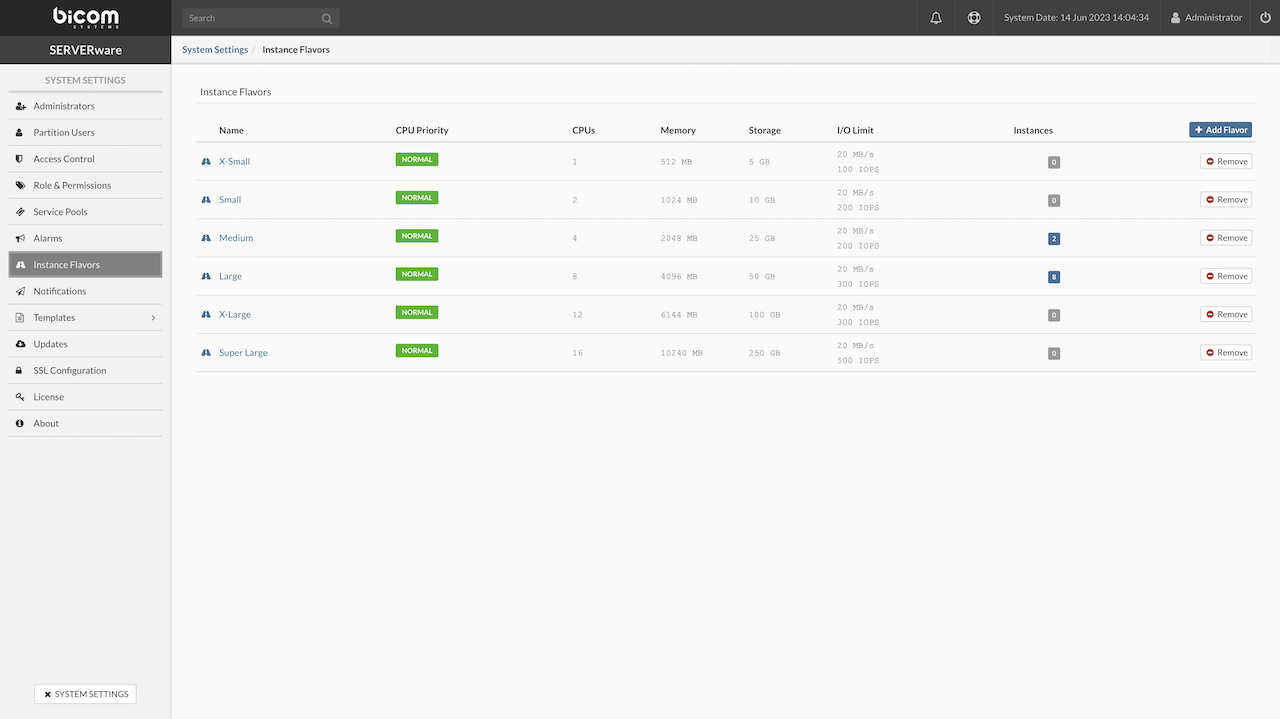
¶ Adding Flavor
To add a flavor, follow these steps:
-
In the Flavors view, click Add Flavor. The Add Flavor dialog will appear.
-
Enter a Name, select the CPU Priority, set the CPU limit, define the amount of Memory, Storage, Bandwidth, and IOPS limit as needed.
-
Once all the configurations are set, click Create to create the new flavor.
¶ Removing Flavor
To remove a flavor, follow these steps:
- In the Flavors view, select Remove Flavor from the dropdown menu next to the flavor to be removed.
- A confirmation dialog will appear. Click Yes to remove the flavor from the list.
¶ Notification Delivery (SMTP)
To properly configure SMTP settings, enter all the necessary SMTP details and click Save. Once saved, the settings can be tested by clicking the Send test e-mail button. If an SMTP server that doesn't require user credentials for authentication is being used, set the Authentication option to "Open". If the SMTP server does not support SSL from the beginning, change the Encryption type to "None". When encryption is set to "None", the SERVERware SMTP client will automatically switch to encrypted mode if the SMTP server supports STARTTLS; otherwise, the connection will remain unencrypted. If sending a test email fails, the relevant error message will be displayed in the system logs view.
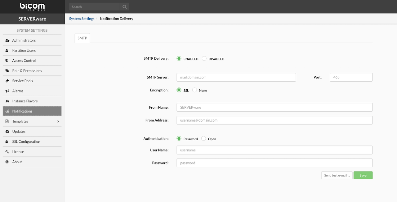
¶ Templates
Templates in SERVERware are standardized software packages used to create and deploy new virtual servers (VPS). Whether deploying a PBXware instance or another application, templates provide a consistent base image for streamlined and reliable initialization.
Starting with version 4.7, SERVERware fully adopted the OCI (Open Container Initiative) format for templates. This shift improves security, simplifies updates, and ensures compatibility across environments by aligning with widely accepted container standards.
Templates are now categorized into:
-
Official – Verified and maintained by Bicom Systems
-
Community – Shared by users for wider use
-
Third-party (OCI) – Pulled from external OCI-compliant sources
¶ Official Templates
Official templates are software packages built and maintained by Bicom Systems. They're tested for stability and performance and are fully supported, which makes them the most reliable option when setting up services like PBXware or sipPROT in SERVERware.
These templates can be downloaded, installed, or removed directly from the interface. Since they're kept up to date by Bicom, any fixes or improvements are delivered regularly, helping to keep things secure and running smoothly.
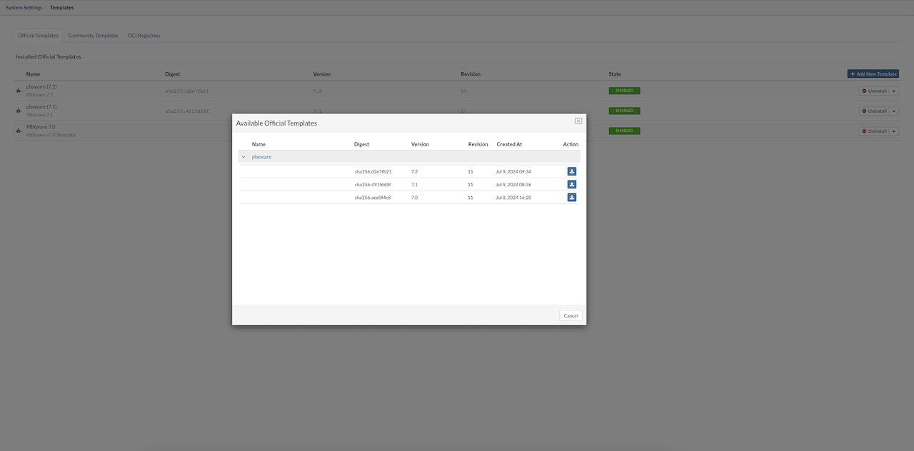
¶ Community Templates
Community templates include third-party software made available for easy deployment within SERVERware. These templates aren't created by Bicom but are provided to expand the range of available software that can be installed with minimal effort.
To add a community template, use the Add New Template button. This opens a list of available templates, showing the version number, creation date, and download option. If a newer version becomes available, an update button will appear, allowing for a quick upgrade.
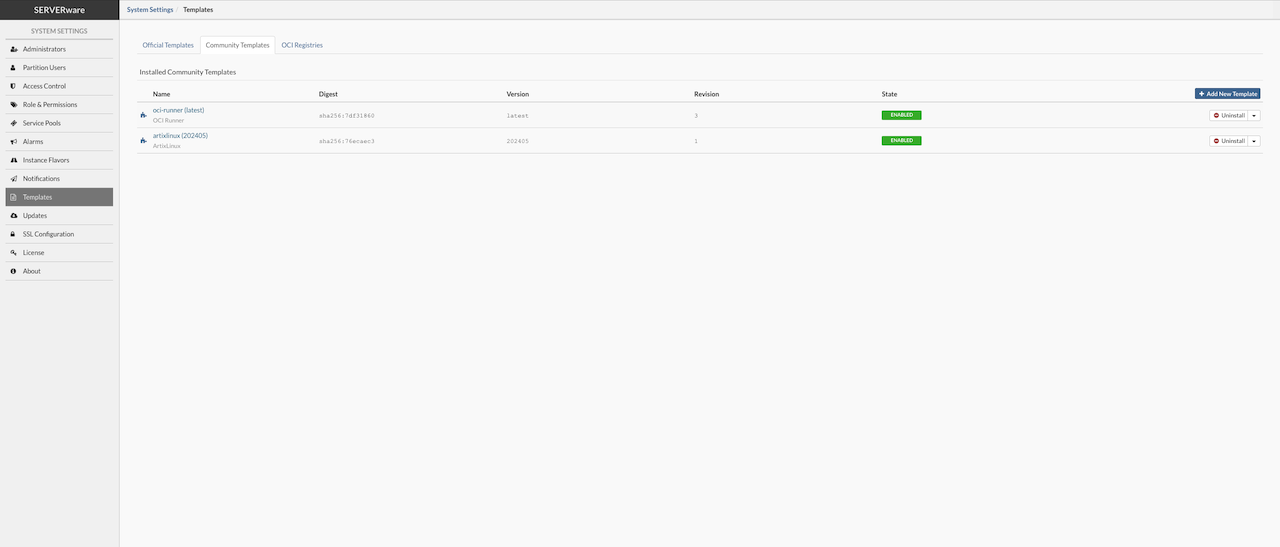
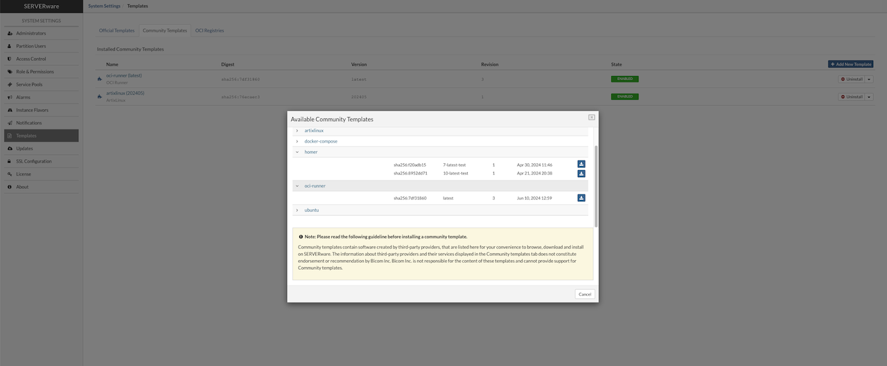
Both official and community templates are hosted on the main repository: registry.bicomsystems.com, keeping everything centralized and easy to manage.
Example - Community Template: Homer
Homer is an open-source VoIP and RTC Capture Framework for Analysis and Monitoring based on the HEP/EEP protocol. Homer supports advanced IP, RTP/RTCP Reports, RTC events, and Custom protocols, and provides various methods of processing logs, metrics, and traces, including Packets and PCAP. For more information on Homer, visit sipcapture.org.
To use Hommer with the PBXware users will need to edit PBXware manually:
- Asterisk 12 and above has a native HEP module that would be able to send SIP/RTCP/TLS data to Homer directly.
- Editing /opt/pbxware/pw/etc/asterisk/hep.conf to point to user's homer server would be all thats needed, for example:
;
; res_hep Module configuration for Asterisk
;

; All settings are currently set in the general section.
[general]
enabled = yes                       ; Enable/disable forwarding of packets to a
                                   ; HEP server. Default is "yes".
capture_address = 10.1.100.60:9061 ; The address of the HEP capture server.
capture_password = foo             ; If specified, the authorization passsword
                                   ; for the HEP server. If not specified, no
                                   ; authorization password will be sent.
capture_id = 1234                  ; A unique integer identifier for this
                                   ; server. This ID will be embedded sent
                                   ; with each packet from this server.
Once done, restart asterisk and confirm the module is sending the HEP traffic by doing a tcpdump towards the homer server. Please keep in mind that HEP will send the unencrypted traffic, so this should be sent over a dedicated/private network if possible.
NOTE: Under SERVERware Community templates, both Homer 7 and Homer 10 will be available to download and install.
Please note that software installed from the Community templates, as well any other third-party software installed from the OCI registries tab, is not supported by Bicom Inc.
¶ OCI Templates
In the OCI Registries tab, administrators have the option to add additional repositories beyond the Official and Community sources. This allows access to a wider range of OCI images from third-party providers or private registries. By adding these custom registries, it becomes possible to download and install software packages that may not be available in the default repositories, offering greater flexibility and control over the templates used within SERVERware.
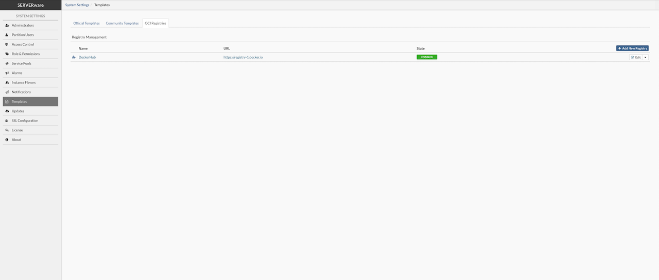
To add a new repository, click the “Add new registry” button, then enter the registry's URL and assign a name. If the registry is private and requires login credentials, username and password can also be entered. The OCI Registries tab includes a connectivity test feature to ensure SERVERware can successfully connect to the added registry.
⚠️IMPORTANT For security purposes, it is recommended to create a read-only access token when working with a private repository. This minimizes risk by limiting the token's permissions to only what is necessary.
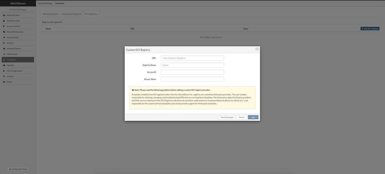
Once templates are downloaded, they can be used to create new VPS instances.
SERVERware provides an OCI runner template that sets up a Docker container engine automatically. This template pulls and starts the selected OCI image. When a new version of the template is available, an Update button will appear.
Deploying third-party OCI images is now simpler and done through the Create VPS dialog after adding the OCI registry.
Selecting the OCI option in the Create VPS dialog changes the view to show fields for the registry, image name, and tag, making it straightforward to deploy the chosen OCI image.
OCI images containing desktop operating systems are not supported. The SERVERware environment is optimized for server-oriented tasks and does not support the rendering or management of graphical interfaces typically found in desktop environments.
¶ Updates
The Updates section in System Settings manages updates for SERVERware components. It displays a list showing each component's Name, Current Version, and the Latest Version available for update.
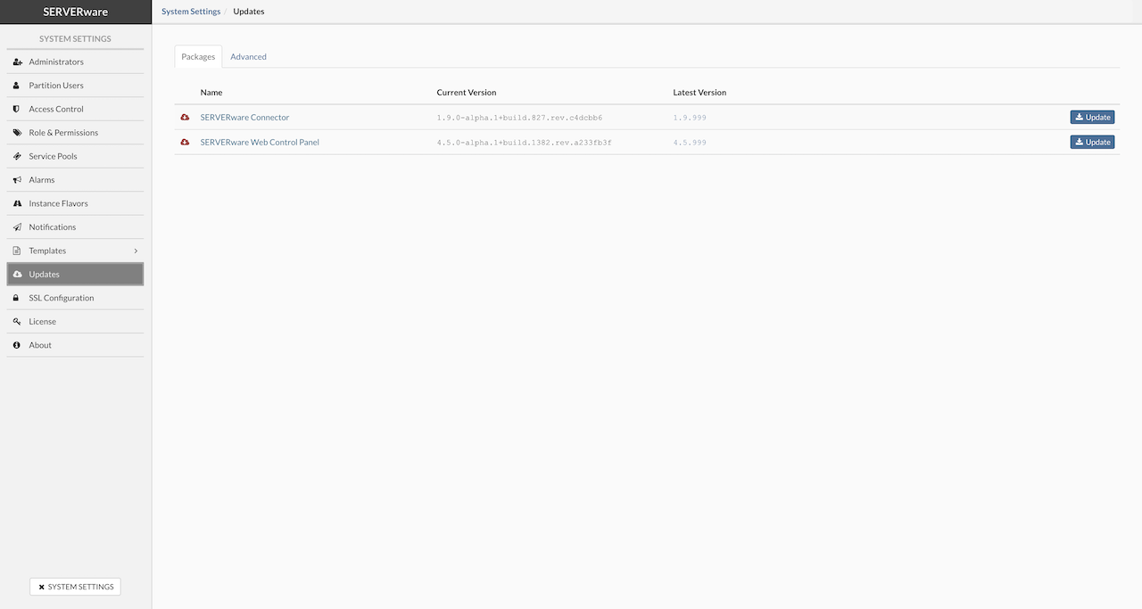
The SERVERware controller automatically checks for package updates every day. When an update is found, a notification pop-up appears at the top of the GUI each time an admin logs in. This pop-up stays for 10 seconds and includes a link to the update page if the admin wants to proceed. Additionally, system administrators will receive email alerts about new available updates.
Update SERVERware Component
To update a SERVERware component, go to the Update section from the main navbar. Find the component in the list and click the Update button on the right. After confirming in the popup window, the update process will begin.
⚠️IMPORTANT When multiple component updates are available, always update the SERVERware connector first before proceeding with other updates.
¶ Updating Host SW-Connector
The sw-connector service agent is a vital part of the SERVERware environment, responsible for maintaining proper communication between hosts and the system. When an update is available—often including important fixes or new features—it should be applied promptly.
Before updating the sw-connector, the host must be placed into Maintenance Mode to ensure a safe update process.
In the Host view, a small question mark icon displayed next to a host indicates that an sw-connector update is available for that system.
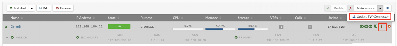
To update the sw-connector, follow these steps:
-
In the Host view, select the host that requires the sw-connector update.
-
Place the host into Maintenance Mode.
-
Click the Update SW-Connector button.
-
Open the System Logs to monitor the update progress.
-
Once the update finishes, click Enable to bring the host back online.
¶ SSL Configuration
SSL ensures that data transferred between systems—such as users and websites—remains secure and unreadable by unauthorized parties. It uses encryption algorithms to protect sensitive information like personal details, login credentials, and financial data during transmission.
The SSL Configuration page displays information about the currently installed certificate and provides options to manage SSL setup. Administrators can manually upload a certificate, generate a Certificate Signing Request (CSR), or use the automatic setup to obtain a free certificate from Let's Encrypt—a trusted, open certificate authority provided by the Internet Security Research Group (ISRG).
There are two ways to install SSL on the SERVERware GUI:
- Automatic installation using a Let's Encrypt certificate
- Manual installation by uploading a certificate and key files directly
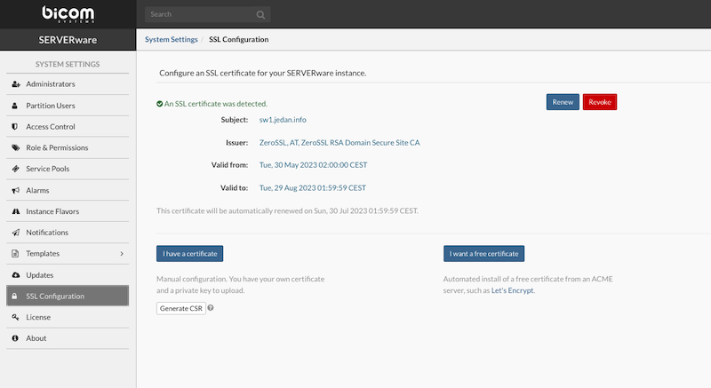
To successfully install an SSL certificate on a SERVERware instance, a valid domain name is required. This domain must be pointed to the public IP address of the SERVERware system, which must be accessible from the internet with port 80 open.
To begin the automatic installation of a free Let's Encrypt SSL certificate, open the SSL Configuration section and click the I want a free certificate button. A popup window will appear to guide the rest of the process.
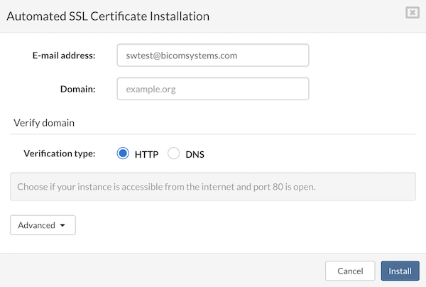
Enter the E-mail address and Domain in the provided fields, then click Install. The system will handle the certificate request and installation. Once completed, the GUI will restart to apply the new settings. SERVERware also supports ACME servers that require External Account Binding (EAB). The automated SSL installation process has been extended to include certificate authorities that use EAB for ACME account registration, such as ZeroSSL and Google Trust Services.
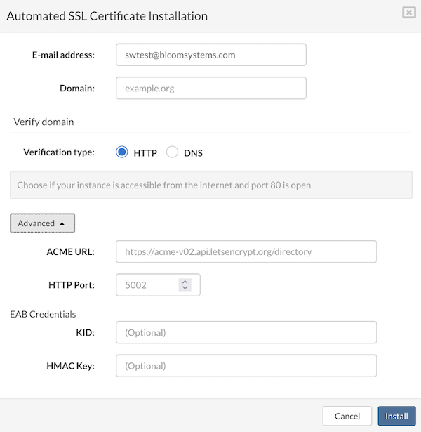
¶ Obtain a Certificate Using Domain Verification Process
Certificates can also be installed automatically using the DNS challenge method. This is useful when the SERVERware instance is not publicly accessible or when using a wildcard domain (e.g. *.example.org).
The DNS challenge can be completed either by manually configuring DNS records or by using SERVERware's built-in CoreDNS feature to handle the process.
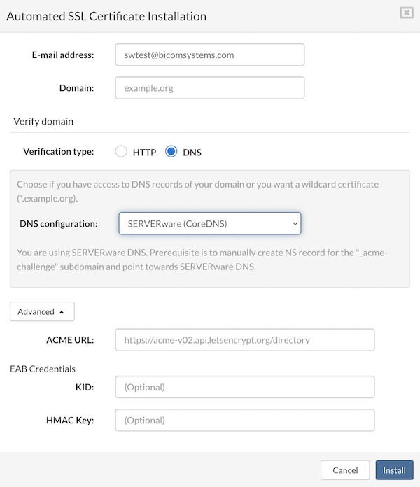
¶ Generating CSR (Certificate Signing Request) from GUI
A Certificate Signing Request (CSR) is a standardized method for submitting a server's public key and associated domain information to a Certificate Authority (CA) to request a digital certificate. This public key is paired with a private key stored securely on the server.
In SERVERware, administrators can generate a CSR and its corresponding private key directly from the GUI for a specific domain. The generated CSR can then be used to purchase and install an SSL certificate from a chosen CA.
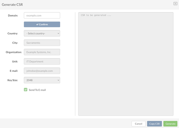
¶ Manual Certificate Upload and Installation
SSERVERware allows uploading of an SSL certificate and private key to replace the default self-signed certificate. To complete the upload, select the .cert file provided by the certificate authority. A private key can also be added—if not selected, the system will continue using the current one. After selecting the necessary files, click Upload to apply the certificate. SERWERware will automatically switch to manually added certificate.
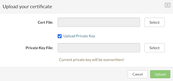
¶ Revoke a Certificate
Certificate revocation is the process of invalidating an SSL/TLS certificate before its expiration date. This is typically necessary if the certificate's private key is suspected to be compromised or if the associated domain is no longer active.
In SERVERware, the option to revoke a certificate is available only for those obtained through the automated method from providers like Let's Encrypt, ZeroSSL, or similar ACME-compatible services. To revoke a certificate, navigate to the SSL Configuration menu and click the Revoke button.
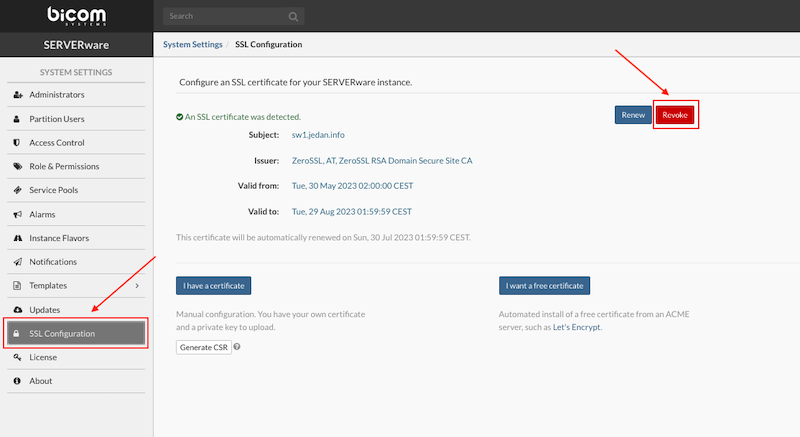
¶ Manual Renewal of Active SSL Certificate
Manual certificate renewal is possible for certificates obtained through automated methods from providers like Let's Encrypt, ZeroSSL, and similar services. To start the renewal process, go to the SSL Configuration menu and click the Renew button. When the popup window appears, confirm by clicking Renew again.
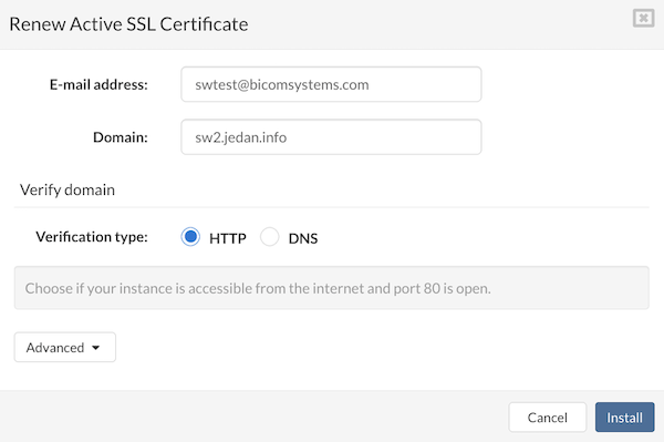
Please wait until the process of renewal is complete and GUI will restart to apply changes.
¶ Observability
SERVERware includes enhanced observability features to provide better insight into platform performance and behavior. With integrated tools such as Prometheus and Grafana, monitoring and diagnostics are more accessible and effective.
¶ Key Features
-
System Metrics with node_exporter
Metrics are collected from both the Controller and all Hosts using node_exporter. This includes essential system data such as CPU usage, memory consumption, disk activity, and more.
-
Prometheus Integration
Prometheus is now built into the SERVERware Controller to collect and store platform-wide metrics. This centralized setup ensures consistent data collection and simplifies monitoring across the infrastructure.
-
Dynamic Configuration
Prometheus supports dynamic target discovery, allowing new components to be monitored automatically without requiring manual configuration changes.
-
Grafana Dashboard
A custom Grafana dashboard tailored for SERVERware environments is available. Once imported, it provides clear visualizations of collected metrics, aiding in performance analysis and system health monitoring.
-
Access Protection
Prometheus endpoints are secured with basic authentication, ensuring that access to monitoring data is restricted to authorized users only.
These observability improvements offer users a more flexible, secure, and comprehensive view of the SERVERware environment. With real-time metrics and visual dashboards, it becomes easier to detect potential issues and maintain optimal system performance.
¶ Enabling and Configuring Observability in SERVERware
To enable or disable the observability feature in SERVERware, go to System Settings > Observability. When observability is turned on, SERVERware starts collecting Prometheus metrics from each host and provides a data source endpoint for use in Grafana.
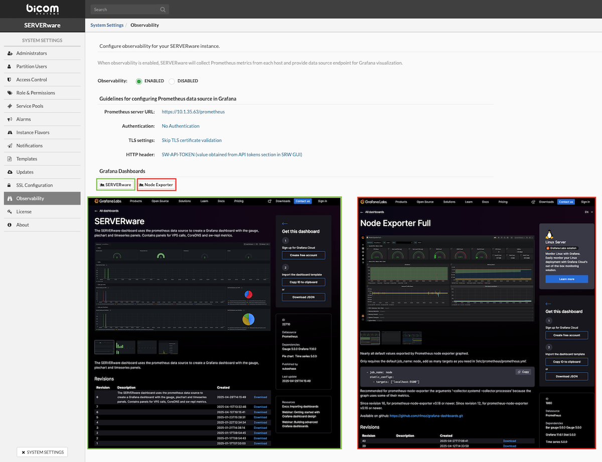
Before the feature can be used, the Prometheus data source must be set up in Grafana. The Observability section includes the connection details needed for this setup, along with simple instructions for importing and using Grafana dashboards built for SERVERware.
¶ License
The License menu displays information about the currently installed SERVERware license and allows updating or changing it. If the license changes, click Update License, enter the new valid license number in the text box, and click Apply. This will refresh the list of features available on the SERVERware instance.